RME ADI-2 Pro : a Technical Overview
Some time ago, I wrote a fairly comprehensive review of the MOTU Microbook II. This little “pro” unit had quite a few tricks up its sleeve, including the ability to be used as a three-way active crossover. I still use it as a portable bus-powered solution for acoustic measurement.
Fast-forward a few years, and I found myself intrigued by a somewhat different interface from the pro-sound world. The RME ADI-2 Pro is a line-level convertor and audio interface, billed as RME’s “reference” A/D and D/A convertor. In addition to a flexible set of analog and digital I/O, it has a solid complement of onboard processing and two powerful headphone amps.
This device was intriguing to me not just because of its audio processing functionality but because of its potential to be used for measuring other audio equipment. In this article I’ll provide an overview of this unit from the perspective of a technically-inclined audiophile. The ADI-2 Pro has more features than I can cover even in overview, so for full details I recommend referring to the comprehensive user manual.
Please note that this is not a subjective listening review.
Contents of this article
- Overview
- I/O
- Signal routing and modes
- EQ
- Some basic measurements
- Implications for measurement
- Limitations for audio playback
- Diagnostics
- Concluding remarks
Overview
RME say the ADI-2 Pro is a “host of devices all put together into one unit.” I like to summarize it as an interface and router between analog signals, digital signals, and a computer connected via USB:
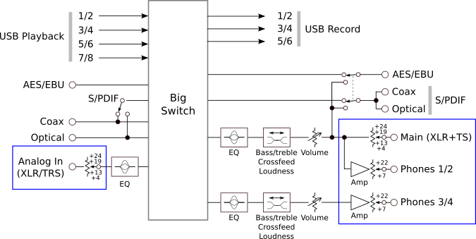
The “Big Switch” in the middle is the key to understanding the operation of the ADI-2 Pro: it routes audio channels coming in from the left of the diagram to channels that go out on the right. I’ve omitted blocks for the ADC and DACs, but outlined the analog sections in blue. Note that the reference levels for a 0 dB FS signal are set in the analog domain on both inputs and outputs, but volume control relative to the reference levels is done in the digital domain in 0.5 dB steps.
All eight USB Playback and six USB Record channels are active when the ADI-2 Pro is set to multichannel USB mode. In this case, sample rates top out at 192 kHz. In stereo USB mode, only USB channels 1/2 are active but sample rate is up to the headline 768 kHz.
There’s a healthy complement of onboard digital processing, some of which is indicated on the block diagram: clock sync/regeneration, sample rate conversion, parametric EQ, bass/treble control, cross-feed, loudness compensation, and more.
I/O
Analog
Analog input is balanced, via combo XLR/TRS jacks. These have a switchable reference level of 4, 13, 19, or 24 dBu, or about 1.2, 3.5, 6.9, or 12.3 Volts RMS. This is a hardware selection – you can hear the relays click when you switch levels.
The Main Out is provided on XLR (balanced) and TS (unbalanced) jacks. These also have a switchable reference level of 4, 13, 19, or 24 dBu, although the TS outputs are limited to 19 dBu.
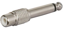
Using the ADI-2 Pro with RCA cables is a simple matter of plugging in RCA-TS adapters – any music supply store will have these:
Digital
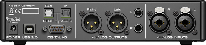
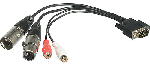
Two optical connectors that support S/PDIF and ADAT input and output are located on the rear panel. AES/EBU and coax S/PDIF connectors are attached via a DB-9 breakout cable:
All digital I/O operates at sample rates up to 192 kHz. Usually, all three digital outputs carry the same signal.
Headphones
Each of the two headphone outputs on the front panel has its own “Extreme Power” headphone amplifier. These have switchable analog reference level settings of 7 and 22 dBu (1.7 and 9.8 Volts RMS). Output current is limited to 260 mA at lower headphone impedances, so power delivery maxes out at about 1.5 Watts per channel at 32 ohms for a normal unbalanced connection and 3 Watts per channel at 64 ohms in balanced headphone drive mode.
Signal routing and modes
The ADI-2 Pro runs completely standalone – that is, it is configured and controlled entirely from the front panel. This is in contrast to many of RME’s other interfaces that are configured with a program called TotalMix, which is used to mix and route inputs to outputs in arbitrary ways.
Because it is controlled entirely from the front panel, however, RME have taken a different approach with the ADI-2 Pro. It has several “modes” of operation, each of which is a bit like a template for routing input signals to outputs. In fact, I delayed purchase of the ADI-2 Pro because I felt I had to study the manual carefully to make sure that everything I would need to do was covered by one of these modes. I needn’t have bothered: in practice, the ADI-2 Pro has not only done everything I’ve needed but it’s smart enough that the default “auto” setting is usually suitable – and if not, there’s a way to change it to what you need.
There are five of these modes, and each is a little different depending on whether the USB class-compliant mode is set to stereo or multichannel. Here, for example, is an illustration of the signal routing in USB stereo mode:
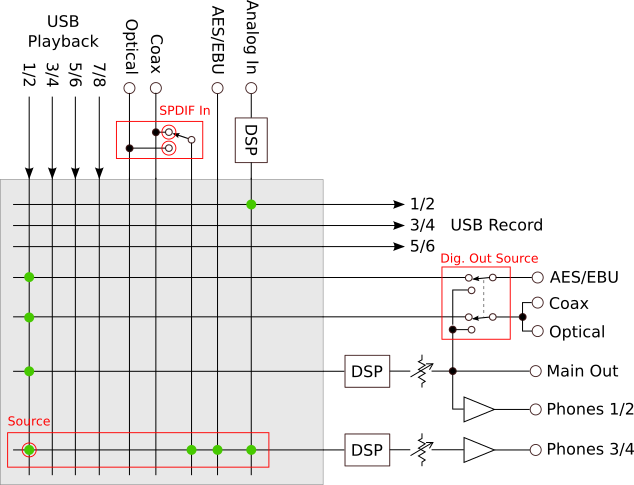
I have redrawn and simplified the block diagram, with inputs positioned along the top. A green dot at an intersection says that the input signal is routed through to the output signal. For example, USB Playback 1/2 at the top left is routed to all digital outputs, Main Out and Phones 1/2. In the other direction, Analog In at the top right is – after digitization and processing – routed to USB Record 1/2.
The digital outputs can be switched to use the same signal as Main Out by changing the Dig. Out Source parameter found in the menus. This enables the digital outputs to have volume control and processing like parametric EQ applied to them and would be used, for example, when feeding monitors with digital input.
The Phones 3/4 output can be fed from four different input signals: USB Playback 1/2, the SPDIF input, the AES/EBU input, or the Analog In. This selection is controlled by the Source parameter in the menus.
USB stereo mode is the default mode, and perhaps the simplest to use. It’s all that’s needed to use the ADI-2 Pro as a desktop headphone amp, for example, and is also the right choice for running analog audio measurements. For a breakdown of all the modes, see the separate article RME ADI-2 Pro : Modes and Audio Routing.
EQ
The analog input and both pairs of analog outputs each have a five-band parametric EQ. The outputs also have bass and treble shelving filters with adjustable Q and turnover frequency. The capabilities of the EQ have been enhanced since the unit was first released; here is the current set:
- Low pass, high pass, peak/cut, low shelf: frequency 20.0 Hz – 20 kHz
- Peak/cut: frequency 20.0 Hz – 20 kHz
- Peak/cut: frequency 20.0 Hz – 20 kHz
- Peak/cut: frequency 200 Hz – 20 kHz
- Low pass, peak/cut, high shelf: frequency 200 Hz – 20 kHz
All filters have gain adjustable +/- 12 dB and Q 0.5 to 5. [Update: as of December 19 2018, Q can be set up to 9.9 on bands 1 to 3. RME continues to improve the ADI-2 Pro in response to user feedback.] Note that bands 4 and 5 have a minimum frequency setting of 200 Hz. The high pass and low pass filters are 12 dB/octave, but within this limitation it’s possible to use band 1 on both pairs of outputs to implement a stereo two-way active crossover.
I’ve used the EQ mostly for headphones though. Since getting the ADI-2 Pro I’ve spent quite a lot of time EQ-ing headphones. Once I met with some success, I felt much less desire to keep different “flavors” of headphone around and I’ve now sold most of them.
Some basic measurements
One of my main justifications for purchasing the ADI-2 Pro is its potential to be used as a measurement front-end. This is where the switchable analog reference levels come in: since an ADC or DAC has lower distortion when run somewhat lower than maximum signal, we can adjust levels to minimize distortion from the measurement equipment and thus improve measurement resolution.
For example, for the following distortion spectrum I set the output reference level to 4 dBu and generated a sine wave at -1 dB FS. The signal level is therefore 3 dBu or 1.1 VRMS. The analog output is looped back directly to the analog input, which is set to a reference level of 13 dBu. Because the ADC is driven well below its full scale, the largest contribution to distortion should be the DAC:
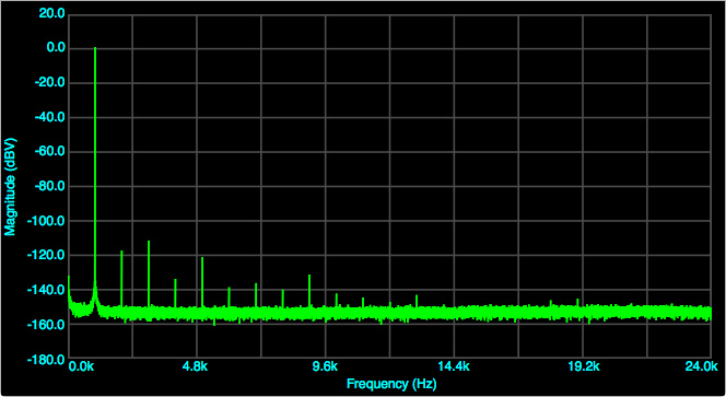
According to Electroacoustics Toolbox, THD is -111 dB. The result here is very similar to the D/A distortion graph in section 34.13 of the user manual, with distortion levels only slightly higher. This gives me confidence that I am basically doing things right.
What if the level from the DAC is reduced? At -4 dB FS, the distortion looks like this:
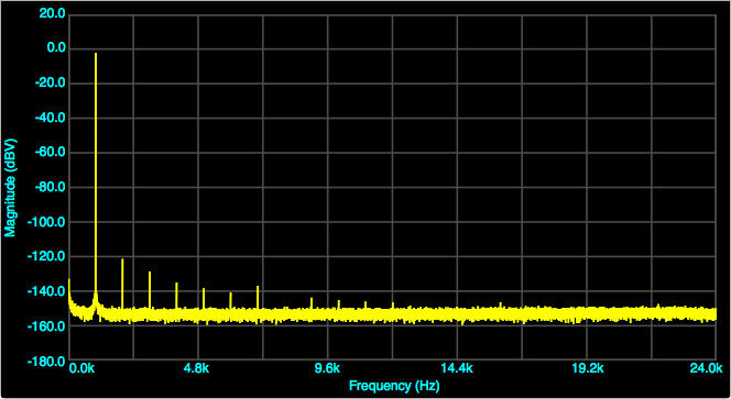
Electroacoustics Toolbox calculates this as a THD of -118 dB. Reducing the level further doesn’t reduce THD any more. The takeaway from these basic loopback tests is that careful use of the hardware reference and digital signal levels can reduce the intrinsic distortion for measurements to a very low level.
Now on to frequency response. Here is the loopback frequency response as measured by FuzzMeasure Pro at sample rates of 44.1 (red), 96 (green), 192 (blue), 384 (orange) and 768 (mauve) kHz, with the “Short delay sharp” filter selected for both the DAC and the ADC:
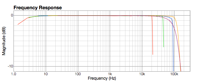
Remember that this is a loopback and so includes the response of both the DAC and the ADC. Even so, the low frequency response is only 1 dB down at 2 Hz. One surprise here is that the response at 768 kHz sample rate rolls off earlier than the 384 kHz and even the 192 kHz sample rates.
Here is the same set of graphs with the “Short delay slow” filter selected for both DAC and ADC:
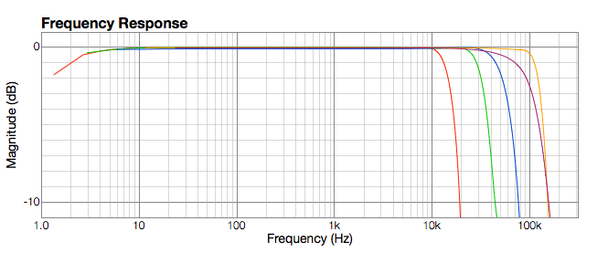
These filters provides a cleaner impulse response than the sharp filters, but they do roll off quite a bit earlier. In the case of the 44.1 kHz filter, the manual shows that the DAC itself is down about 5 dB by 20 kHz. Note also that the 384 and 768 kHz filters are the same regardless of whether sharp or slow filter is selected.
Implications for measurement
From the frequency response graphs above, the optimum sampling rate for measurements at high frequencies is 384 kHz. RME have in fact added a digital filter that runs only at the 384 kHz rate and corrects the response of the DAC to be flat (-1 dB) up to 115 kHz. The minor trade-off is that, if generating a signal above 90 kHz, the output level must be kept at -4 dB FS or below. Not difficult when 0 dB FS can be as high as +24 dBu. The ADC is flat to 124 kHz (-1 dB, again per spec.).
With that said, so far I have found that I am mostly conducting measurements at 96 kHz, using the “sharp” filter. These measurements are intended to characterize noise and distortion in the audio band and a bit above, so extreme bandwidth is not required. The two distortion spectra above are an example.
Limitations for audio playback
While the ADI-2 Pro will play back files with a sample rate of 768 kHz, the graphs suggest there isn’t much point. This is an interesting punctation mark to the race for higher sample rates: the DAC chip manufacturers (I refer to Asahi Kasei in this instance not to RME) will let you feed their DACs at those rates, but the DAC won’t reproduce up to Nyquist anyway.
One of the great features of the ADI-2 Pro is its inbuilt EQ. However, EQ is done with DSP, and DSP needs compute cycles to, well, compute the EQ. So the higher the sample rate, the less EQ-ing can be done. The ADI-2 Pro maintains its full suite of processing up to 192 kHz. At 352 kHz and above, you can have only one EQ block. This is OK for say headphones as long as you have remembered to switch off the EQ on the analog input and main output. However, you will still lose the bass and treble controls. At 705 and 768 kHz, you lose the cross-feed as well.
Since I like EQ and bass/treble adjustment on my headphones, I find 192 kHz to be the practical limit to sample rate for audio playback. (Besides, I can’t hear much above 90 kHz anyway. Age-related, I guess.)
Be aware of this DSP compute limit if you upsample your files in your music player or server. If you compare playback at the native sample rate to upsampling to, say, 768 kHz and think “oh that sounds real different,” double-check what processing is still enabled at the higher rate….
Diagnostics
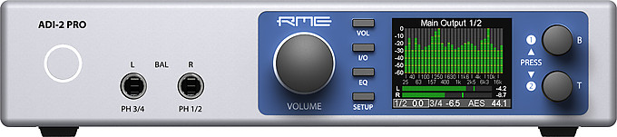
When listening through the ADI-2 Pro, I usually display the spectrum analyzer screen:
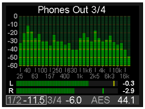
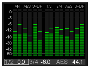
Apart from the obvious spectrum analyzer and meters, the lower section displays the volume settings for both pairs of outputs and the clock source and sample rate. There is a separate screen with level meters for all inputs and outputs (but not USB), useful when performing measurements or figuring out why you’re not getting audio:
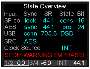
Finally, the State Overview screen has more detail on the digital sources and clock rates:
Concluding remarks
I’ve been using the RME ADI-2 Pro for over six months now. The combination of low distortion, absence of power supply or USB noise, analog reference levels switched in hardware, precise volume control, extensive onboard processing and a “just right” set of I/O jacks make it a great toolbox for the technically inclined audiophile, whether for measuring or evaluating other equipment or just for listening.
There are also a lot of convenience features that I haven’t mentioned. For example, when displaying the spectrum analyzer, the larger knob controls volume and the two smaller knobs to the right of the display control bass and treble. To switch between headphones out and main out (to send audio to speakers), a half-second press on the volume knob mutes one and enables the other. With that said, it is quite a complex product, so expect to spend some time studying the user manual, perhaps even before purchasing. Getting the most from this powerful and versatile unit means learning to use its extensive array of features to good effect.
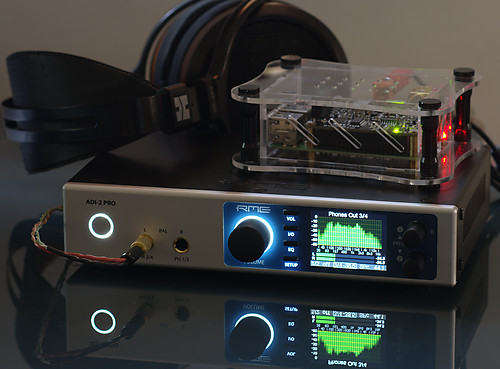
The RME ADI-2 pro is compact enough to fit almost anywhere. Here I am using it as a desktop headphone rig, accepting audio not via USB but via an Allo DigiOne SPDIF card on a Raspberry Pi.


Enjoyed the review and, especially, the measurements. Have you thought about doing the same for the new little brother, the ADI-2 DAC? There are, supposedly, some minor improvements in this offspring.
Hi Craig, thanks for the comment 🙂 I put a brief comparison of the ADI-2 DAC with the Pro on my blog here: https://johnr.hifizine.com/2018/08/rme-adi-2-pro-vs-adi-2-dac/. As far as I know, the main improvement in the DAC over the Pro is the “femto” clock. This is now part of the ADI-2 Pro FS. I see the ADI-2 DAC as largely being a subset of the ADI-2 Pro FS, except perhaps for the IEM output and remote control.