RME ADI-2 Pro : Modes and Audio Routing
In the article RME ADI-2 Pro: A Technical Overview, I referred to the various operational modes of the ADI-2 Pro and gave a diagram showing the routing of audio for its stereo USB mode. I omitted detailed explanation of the other modes.
In this article, I’ll provide routing diagrams for the other modes. The presentation is a bit terse, in order to stay focussed on the essential aspects of each mode. Note also that all of this information is already in the user manual; however, I find these diagrams useful for myself to answer questions about the modes and their routing so others might too.
Contents
- Context
- USB Stereo mode
- USB Multichannel mode
- AD/DA mode
- Preamp mode
- Digital Thru mode
- DAC mode
- Clocking
- Closing remarks
Context
The ADI-2 Pro runs in one of five basic modes: USB, AD/DA, Preamp, Digital Thru, and DAC. There is also a setting for USB class-compliant mode, which can be set to stereo or multichannel. The combination of these two mode settings determines how signals are routed within the “Big Switch” in this block diagram (from the Overview article):
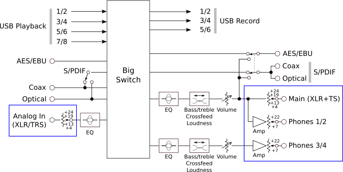
To more easily illustrate what happens in the Big Switch, I have redrawn the block diagram with the inputs along the top and simplified the processing blocks:
![]()
For each mode or mode combination, I will annotate this diagram to show the routing it is capable of:
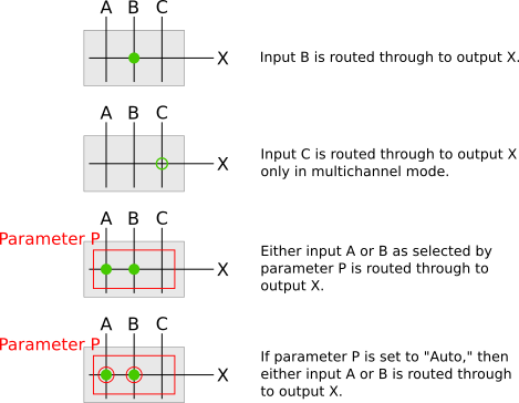
The following sections present diagrams that show the possible routing for various modes. While the diagrams most obviously indicate routing from inputs to outputs, the choices of default and auto-switched routing (red circles on the cross-points) is also an important distinguishing feature. I use these diagrams to figure out which mode I need to use for a particular situation, or conversely, to remind me exactly which signals go where in a given mode.
While the routing diagrams show where audio can go, there is another aspect to successful use, which is the selection of the clock source. For the most part, discussion of this is deferred to the later section “Clocking“.
USB Stereo mode
USB Stereo (basic mode is USB, class-compliant mode is stereo) is the ADI-2 Pro’s default mode setting. The routing is fairly typical of stereo USB audio interfaces – that is, USB audio from the computer goes to the analog output and analog input goes to the computer via USB:
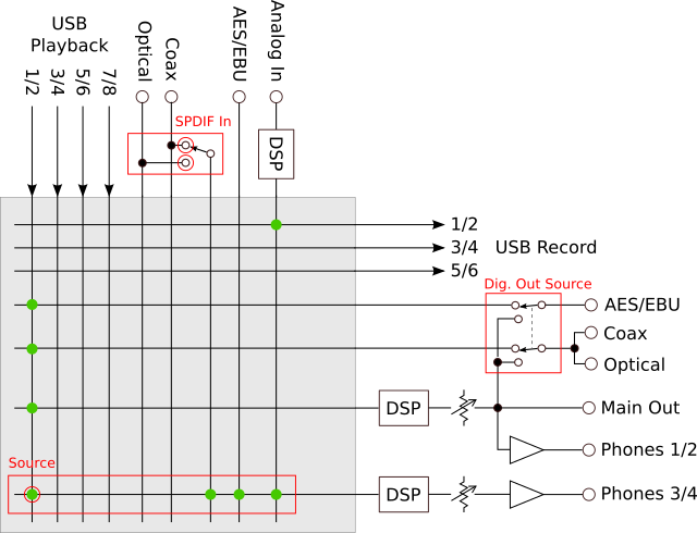
In the ADI-2 Pro, USB audio from the computer also feeds the digital outputs. The Phones 3/4 output carries USB audio by default, but can also be used to monitor the analog or digital inputs – this ability of Phones 3/4 to monitor any input is a common characteristic of most modes.
Sample rates up to 768 kHz can be used in stereo mode. However, the digital inputs and outputs are disabled for sample rates greater than 192 kHz. (There is an exception: at 352.8 and 384 kHz, and provided Dig Out Source is not set to Main Out, USB channel 1 is multiplexed to both channels of the digital outputs. This is called SMUX and is useful – according to the user manual – with certain types of test equipment.)
USB Multichannel mode
In USB Multichannel mode (basic mode is USB, class-compliant mode is multichannel), all inputs and outputs are directly accessible to the computer via USB:
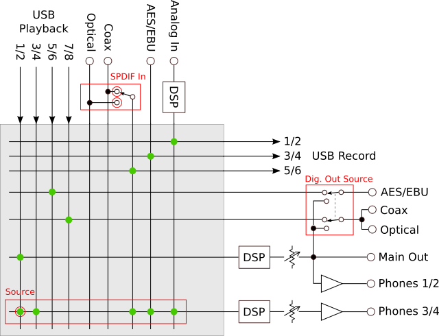
This is the mode I usually use when using the ADI-2 Pro for testing other equipment, as it makes it easy to route signals of all types to and from the computer. If recording digital inputs to USB, some attention may need to be paid to clock settings – see the section “Clocking” later in this article.
This is the only time I provide a separate diagram for multichannel class-compliant mode. In the other basic modes, multichannel is a superset of stereo, at least as far as routing is concerned.
Additional notes:
- Sample rate is limited to 192 kHz.
- This is the only mode combination in which the AES/EBU output signal can be different to the SPDIF output signal.
- This is the only mode combination in which USB Playback channels 5 through 8 are routed anywhere. Note, however, that they can’t be monitored on Phones 3/4. This is a conscious design decision by RME that is intended to minimize user confusion when switching between this mode and other modes that don’t support USB Playback 5-8.
- By default, Phones 3/4 carry USB Playback 1/2, but USB Playback 3/4 can be manually selected.
AD/DA mode
In AD/DA mode, Analog In is routed by default to all digital outputs and the active digital input is routed to the analog outputs:
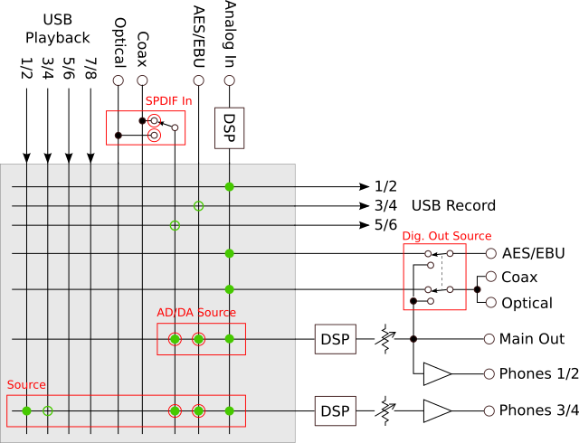
The ADI-2 Pro is therefore acting like a “traditional” A/D and D/A convertor, but with a lot more flexibility and with the addition of DSP capability. The computer can be used to record the analog input, and also the digital inputs if in multichannel class-compliant mode.
Additional routing in multichannel class-compliant mode is shown as open green circles. Specifically, the digital inputs are routed to USB, and USB 3/4 can be monitored over Phones 3/4. This also applies to all following sections.
Preamp mode
Preamp mode is for use when the analog input is the primary or only input. By default, Analog In is routed to all outputs:
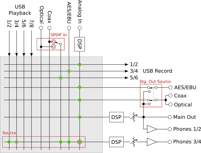
While the routing is a subset of AD/DA mode, the default/auto selection is the analog input. Switching to Preamp mode can in some cases be an alternative way to switch between digital and analog inputs.
If no computer is connected, the operating sample rate is set by the Sample Rate parameter (Setup → Options → Clock). If a computer is connected, then the sample rate set by the computer for the USB interface determines the operating sample rate.
Digital Thru mode
In Digital Thru mode, the active digital input is routed by default to all digital outputs:
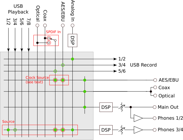
This is the only mode that routes digital inputs directly to digital outputs. S/PDIF or AES/EBU is automatically selected, depending on the presence of a valid signal, with AES/EBU taking priority. If both inputs are present and both are synced to the internal clock, the Clock Source parameter can be used to manually select the input.
I’ve only used this mode once, when I was trying to drive a recalcitrant active speaker with AES/EBU input from an SPDIF source. Even with an SPDIF to AES/EBU step-up transformer, the receiver wouldn’t lock. Then I remembered I had the ADI-2 Pro to hand – bingo, problem solved by Digital Thru mode! While buying the ADI-2 Pro solely for this purpose would be overkill, the capability does help the ADI-2 Pro earn the “audiophile toolbox” moniker that I gave it in the overview article.
DAC mode
DAC mode makes it convenient to select from any input and route the signal to all outputs simultaneously:
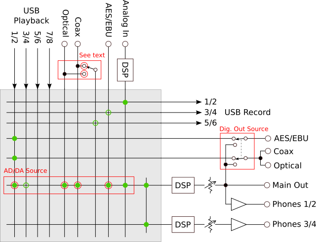
DAC mode is what I usually use when the ADI-2 Pro is sitting on my desk functioning as, well, a DAC. With that said, I have also used the analog input in this mode for a turntable connected to my desktop listening setup. The clock source follows the selected input. In short, this is the easiest mode to use when you need to select from amongst all of the inputs.
Note that Main Out and Phones 3/4 are tied together but still have separate processing (DSP, volume). When I use this mode, I set Dig. Out Source to Main Out, so that the digital outputs mirror the main analog outputs. This way I can quickly switch audio between headphones and active speakers with digital input.
This is the only mode in which the coax and optical S/PDIF inputs are treated as independent inputs – they are selected directly with the AD/DA Source parameter rather than being selected separately with SPDIF In. In multichannel class-compliant mode, USB Record 5/6 carries the selected (coax or optical) SPDIF input; or if neither is selected, then it carries the SPDIF input (provided the clocks are correct – see the next section).
Clocking
In any digital system, there may be more than one digital clock. In the case of the ADI-2 Pro, there are up to three clock sources:
- SPDIF – the clock embedded in the SPDIF input signal.
- AES – the clock embedded in the AES/EBU input signal.
- INT – the clock generated by the internal oscillator. If USB is connected, the connected computer sets the sample rate of this oscillator; if USB is not connected, it is set by the Sample Rate parameter. Digital I/O is disabled if the sample rate is set higher than 192 kHz.
To visualize how the clock source affects audio, consider the following diagram (I’m assuming USB is connected):
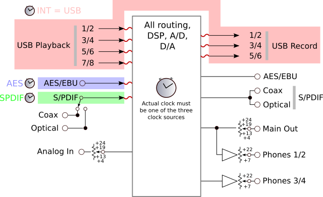
All digital processing – the big box in the middle of the diagram – uses one of the clock sources. The clock source can be manually selected with the Clock Source parameter; or if it is set to Auto, the ADI-2 Pro chooses the clock source based on the basic mode and which of the digital input signals are present.
Whenever a digital signal enters or leaves the box at one of the squiggly red lines, the clock must be the same on both sides of the connection. If not, then the ADI-2 Pro will mute that audio path. Correct clocking is accomplished by observing two rules:
- If using a digital input, either a) the selected clock source must have the same clock as that input or b) that input must have sample rate conversion turned on.
- If transferring data over USB, the sample rate set by the computer must be the same sample rate as the clock source.
Rule 1(a) is usually accomplished by setting the clock source to the desired digital input, but can also be true if both digital inputs have the exact same clock. If 1(a) is true, the State Overview screen will show “sync” for that input. If using both digital inputs at the same time, they must both satisfy Rule 1.
You can still pass audio even if the two rules are not quite followed. For example, I found that audio from the SPDIF input will pass through even if the clock source is set to INT, provided the nominal sample rates are the same. Examining the State Overview screen showed “sync” with an occasional flicker back to “lock” – my conclusion is that the clocks in this particular case are very close and don’t lose sync for long enough for the ADI-2 Pro to decide to turn off audio from SPDIF. However, I expect that in general this is not recommended.
Automatic clock source selection can produce an unexpected result in some cases. For example, supplying an SPDIF signal while in USB Stereo mode will switch the clock source to SPDIF, potentially resulting in no audio. If you are not getting audio even though the routing is correct, check the State Overview screen and use manual clock source selection or sample rate conversion as needed.
Closing remarks
While the ADI-2 Pro is a complex device, the modes simplify signal routing and make setting up the unit for a particular situation quicker. Bearing in mind the requirement that everything in the ADI-2 Pro can be accomplished without a computer connected, the modes can be considered as a sort of shorthand that gets you close to a solution, which you can then tailor by adjusting parameters away from the default or automatic selections.
Acknowledgments
This article was greatly improved by comments from Matthias Carstens of RME and Patrick Dillon.


This is a lot easier to understand than the manual. Many thanks!
About sync and lock state of digital input signal synced to another clock. Just because you get sound from a source synced to a different clock doesnt mean that its nearly optimal. The misalignment of music signal and clock will flatten the sound quite pronounced here in my system, but its good enough that you doesnt notice right away, so this can be a bit of a pain. Only play music from a signal that shows as sync in state overview.