Prototyping a 4-way open-baffle speaker with the miniDSP 2×4
This is the second in a series of tutorials on the miniDSP. In the first tutorial, I introduced the miniDSP 2×4 standalone unit and showed how it could be used for equalizing a subwoofer and integrating it with the mains. For this tutorial, I decided to use the miniDSP 2×4 again, but this time for a 4-way speaker. The speaker is an open-baffle loudspeaker, a configuration that has been gaining popularity in DIY circles in recent years.
After (re) introducing the miniDSP 2×4, I’ll provide an overview of open-baffle speakers, and then proceed to the tutorial part – how to use the miniDSP as a 4-way crossover and equalizer. The emphasis in the tutorial is intended to be on the use of the miniDSP, and not so much on the speaker itself. So I hope that you will find the tutorial useful even if you are using the miniDSP for a more conventional (boxed) 3-way or 4-way loudspeaker.
This article is Part 1 of the full tutorial. In this part, I will get as far as getting the crossover running and some basic measurements and equalization. In Part 2, I’ll present more sophisticated measurement and processing techniques for integrating the drivers. In Part 3, I’ll complete the four-way system with an open-baffle subwoofer.
The miniDSP
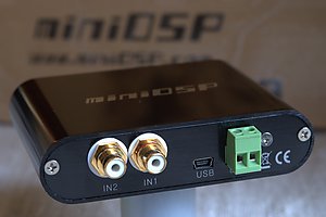
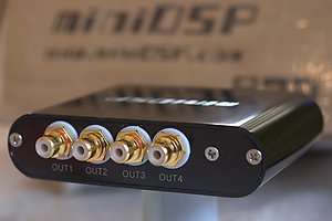
Here is a quick recap of the miniDSP 2×4 unit. Physically, it’s a small metal case, about 110 x 80 x 25 mm in size, with two RCA input connectors and four RCA output connectors. In addition, there is a USB Mini-B connector to use for configuring the miniDSP from your computer, and a DC plug with screw terminals if you wish to use an independent power supply. (By default, the miniDSP 2×4 is powered from the USB connector.)
Inside this teensy little box is an embedded digital signal processor (DSP), along with power supply regulation, a two-channel analog-to-digital converter (ADC), and a four-channel digital-to-analog converter (DAC). The signal processing functionality that the unit performs is determined by the specific software “plugin” that you load into it. There are quite a number of these available from the miniDSP online store.
For this tutorial, we will be using the 4-way PEQ plugin. This plugin turns the miniDSP into a mono 4-way crossover with a raft of parametric equalizers that we will use to correct driver, baffle, and room responses. Thus, for this project, we will need two miniDSP 2×4 units – one per channel.
Although we are using the standalone miniDSP 2×4 unit for this project, the overall miniDSP concept is of a set of modular DSP building blocks. The miniDSP circuit board provides 2-in 4-out processing, and additional boards can be added for S/PDIF I/O, USB input, and even a Class D amplifier module with digital (I2S) connection to the miniDSP. This tutorial is, however, focusing on the crossover and equalization capabilities of the miniDSP, and not the hardware – perhaps future tutorials will demonstrate the integration of the various boards in the miniDSP system.
A little open-baffle speaker theory
In its simplest form, an open-baffle speaker can be constructed by cutting a hole in a sheet of wood (or other material) and mounting a driver in it. Unlike conventional speakers, there is no box enclosing the driver. This has a number of consequences, which largely revolve around the fact that the acoustic energy from the back of the driver’s cone is radiated into the room, as well as the energy from the front of the driver:
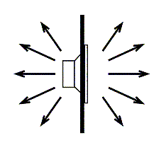
Figure 1. Acoustic radiation from an open baffle speaker
The acoustic radiation from the rear of the cone will interfere (cancel or reinforce, depending on frequency and location in space) with the radiation from the front of the cone. The most notable effect of this interference is that there is a null to the sides of the baffle – that is, the front radiation and the rear radiation cancel each other out along an imaginary line drawn out to either side of the baffle. The result is a “figure of eight” radiation pattern, as shown in Figure 2a.
The grey line on this diagram represents the locations around the speaker where a constant acoustic power is produced. The diagram illustrates that the highest output power is to the front and rear of the speaker, and the lowest to the sides. Theoretically speaking, this shape is caused by two oscillating point sources of opposite polarity – a dipole. So, open-baffle speakers are often also referred to as dipole speakers.
Now, this is an idealised curve, which really applies only at low frequencies. At higher frequencies, the interference between the front and rear waves produces more complex “lobing” patterns, such as in Figure 2b.
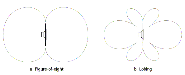
Figure 2. Radiation patterns of an open-baffle speaker
The interference between the front and rear waves has another effect: below a certain point, as frequencies get lower, the total amount of acoustic energy produced gets lower. An open-baffle speaker thus typically needs more volume displacement (cone area ⨉ distance of cone movement) than a box speaker to achieve the same level of output at low frequencies – this is why open-baffle speakers typically have fairly large woofers or multiples of them.
For an idealised “point source” driver on a round baffle, the response curve can be calculated. See this page at Linkwitz Lab for the calculations and explanation of the theory. For the less gifted, we can see the same effects by running a simulation program such as the Edge. Here, for example, is the simulated on-axis response of a very small (1mm diameter) driver in the centre of a 45 cm diameter round baffle (ignore the blue line, it’s not relevant for this discussion):
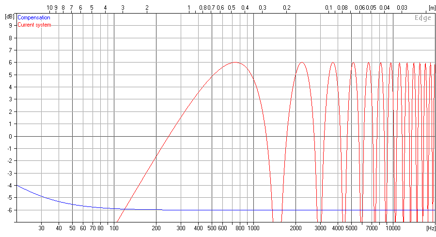
Figure 3. Frequency response of an ideal point source driver in a circular baffle
(Click on this or any of the graphs in this article for a larger version.)
At around 730 Hz, we see what is known as the “dipole peak,” which occurs at the frequency at which the rear wave acts to reinforce the front wave. Below that frequency, the front and rear waves progressively cancel each other out, with the slope of the curve tending towards a drop of 6 dB/octave. Above that frequency, the front and rear waves alternately cancel and reinforce, leading to the “comb” pattern that you see in the plot.
Now, in practice, we don’t put a teensy driver in the centre of a round baffle. As it happens, a realistically-sized driver acts to spread the locations of the cancellation notches, evening out the response to some degree. A non-circular baffle adds to the effect. Here is the simulated on-axis response of a driver with a cone of 13 cm diameter, centred horizontally in a 45 cm wide by 90 cm high baffle, with its centre 30 cm from the top of the baffle:
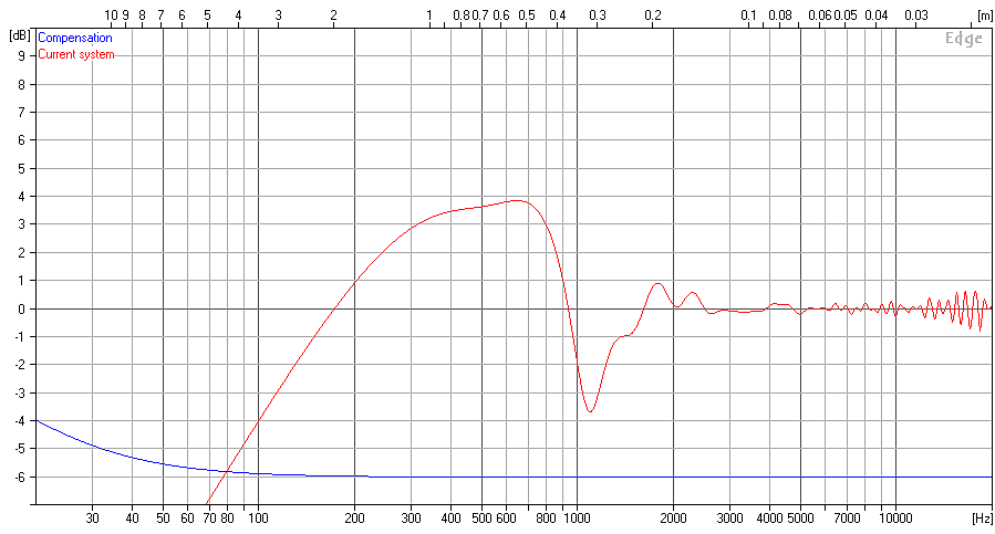
Figure 4. Frequency response of 130mm driver in rectangular open baffle
As you can see, the frequency response is still not exactly flat, and there is a fairly significant notch in the frequency response at around 1100 Hz. But it is better than the point-source driver in the circular baffle.
To summarise: the front and rear waves of an open baffle speaker interfere in a complex way to create patterns of reinforcement and cancellation in frequency and space. One might then be tempted to ask: why bother? Well, because, in practice, it can be made to work remarkably well. Here are some possible advantages of the open-baffle approach:
- Higher direct-to-reverberant energy. As Siegfried Linkwitz explains, the total radiated power from a dipole is 4.8 dB less than from a monopole (equal radiation in all directions), given the same on-axis level.
- Less excitation of room modes. An open-baffle speaker tends to excite room modes less in the direction to the sides of the speaker, where the radiation null occurs.
- No “box sound.” This is controversial, but since there is no box, pressurization caused in that box by the loudspeaker driver can’t excite resonances in the box material. (Resonances in the baffle itself can still occur and can be an issue.)
- More uniform excitation of the reverberant field. A conventional box speaker tends to radiate in all directions at low frequencies, and only to the front at high frequencies. An open-baffle speaker, which radiates to the rear over a greater range of frequencies, can result in a more “spacious” sound.
Loudspeaker design is a complex set of trade-offs and the above list is intended to indicate the kinds of things that could be taken into consideration – they are not absolutes.
The prototype speaker
The fact that a box is not required is one of the fun aspects of making a DIY open-baffle speaker – it’s relatively quick to knock up a prototype to experiment with. This is my second prototype of this particular speaker – I made some mistakes and learned some things with the first prototype, and I will no doubt make more mistakes and learn a few more things with the second prototype!
The overall configuration is a three-way loudspeaker mounted on an open baffle, with the fourth “way” being a separate subwoofer on each channel. One channel is illustrated in Figure 5 (click to enlarge):
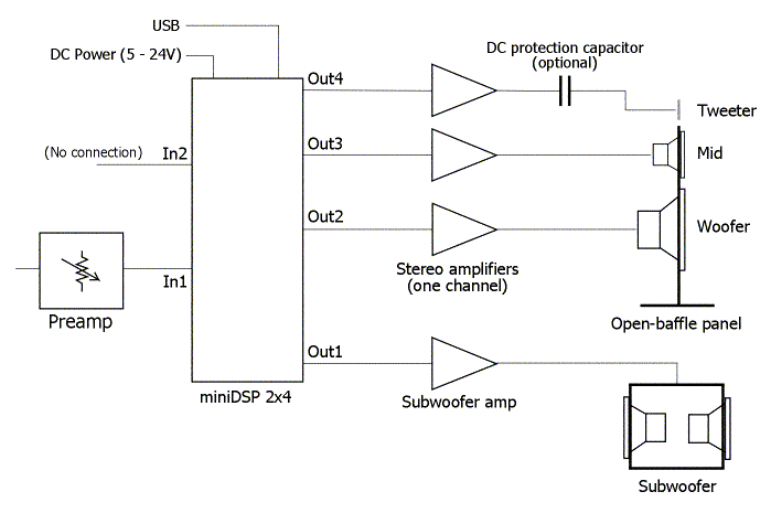
Figure 5. 4-way open-baffle speaker block diagram
The anticipated crossover points are around 400 Hz and 4 kHz, with the subs reinforcing the woofers underneath around 50 Hz. Each channel uses a single miniDSP 2×4 for crossover and equalization. A total of six channels of amplification are needed for the main open-baffle panel, and an additional two channels for the subwoofers.
I am using the “Rev A” version of the miniDSP 2×4. This has a maximum input voltage of 0.9 Vrms, and a maximum output voltage on each channel of 0.9 Vrms. At the input, we must not exceed that limit, or we will get clipping of the input signal. At the outputs, the maximum output level together with the amplifier sensitivity and the driver sensitivity determines the maximum acoustic signal level that can be obtained from each driver.
In general, the topic of matching signal levels with the gain/sensitivity parameters of various units is referred to as gain structure. We don’t want to have signal levels too high anywhere in the chain, or we will get clipping distortion. Nor do we want to have signals levels too low anywhere in the chain, or we may introduce noise. In a typical domestic system, the configuration shown above with the “Rev A” miniDSP 2×4 will most likely work well. There may be cases where the “Rev B” version, with a 2.0 Vrms maximum input level, should be used instead. And, amplifiers with an unusually low or high input sensitivity may not be best suited for this application.
Choosing drivers
Using a miniDSP (or other digital crossover/EQ) is quite liberating for a DIYer, as you have less to worry about in terms of selecting drivers:
- With steep crossover slopes available, you can set a crossover point for a given driver lower than you would if using a passive crossover.
- With powerful and flexible EQ on tap, you can use drivers that you might otherwise avoid because of the need to implement a notch filter or other response shaping.
- With an active system, there is less concern about matching driver sensitivities.
This opens up opportunities to use drivers that you might not otherwise… or for that matter, to re-use drivers that you already have from previous projects… Here are the drivers I am using in this prototype:
- Tweeter. I am using the Bohlender Graebener Neo3-PDR, in “dipole mode” (that is, with the back cup removed). This tweeter is relatively inexpensive, and flexible enough to be used in a lot of different ways. Although I would have liked to use the more sensitive non-PDR version of this tweeter, I already had the PDR version, so I’m using those for now.
- Midrange. This is a hard one, as there are so many possible choices! For this prototype, I’ve gone with the B&C 6PEV13. This is a very sensitive midrange driver designed for pro-audio applications. Since I am planning to set a crossover point at 400 Hz, a mid-bass type of driver with high excursion capabilities is not needed.
- Woofer. Again, a good number of choices, but I’m going to use the Lambda Acoustics (now Acoustic Elegance) Dipole15 woofer, which I’ve used in a different prototype in the past… This woofer is designed specifically for open-baffle applications – it has a high Qts, so it tends to maintain output at lower frequencies (as compared to a similar driver with low Qts, which will roll off at low frequencies without a box behind it).
Designing a baffle
As illustrated above, the baffle shape and the location of the drivers has a very strong influence on the frequency response. Fortunately, there are tools available to help. In particular, the Edge is great for baffle design. Download it and give it a try! (Requires Windows.)
With the first prototype, I found that the measured response of the speaker was quite similar to that predicted by the Edge. So in this (second) prototype, I felt more confident in doing an “advanced” baffle shape based on the Edge simulation. Here is the midrange driver positioned on the baffle:
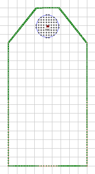
Figure 6. Midrange driver location on the prototype open baffle
The baffle is 45cm wide and 90 cm tall. Conveniently – and not exactly coincidentally – the same size as off-the-shelf sheet material available at the local hardware outlet. Here is the simulated on-axis response of the driver on the baffle (click to enlarge):
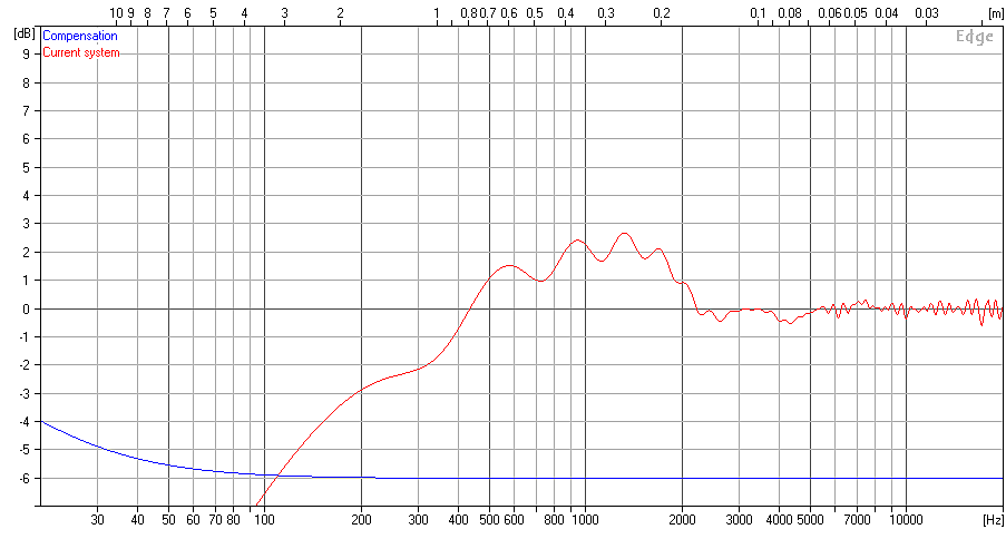
Figure 7. Midrange driver frequency response in the truncated open baffle
Compared to Figure 4, you can see that mounting the driver close to the edges of the baffle reduces output at lower frequencies. However, that nasty notch at 1100 Hz (which no amount of EQ will be able to get rid of) is no longer there. Since the baffle still supports output down to the crossover frequency of 400 Hz, the reduced output at lower frequencies is not a concern.
The location of the woofer is less critical than the midrange. Since I know that these speakers are to be supported by subs, I’ve located the woofer off the floor, and as close to the midrange driver as seems feasible. If there were no subs, I would have located the woofer lower in the baffle in order to take advantage of reflection/reinforcement from the floor.
Figure 8 shows the simulated on-axis response of the woofer. Note, however, that the Edge doesn’t include floor effects in the simulation – in practice, I am expecting more output at low frequencies than the simulation shows.
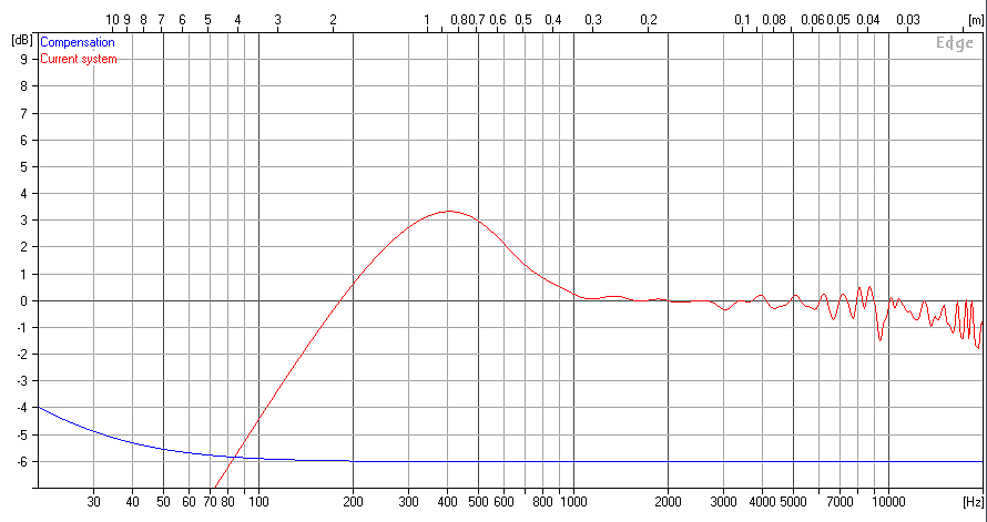
Figure 8. Woofer frequency response on open baffle
Building the prototype
When building any prototype, one should always ask: “What is it that I am going to learn from this prototype”? The prototype should then be built so you can learn those things, and not worry about other things. In this case, the goal is to measure these drivers on a specific baffle shape to determine the optimum crossover settings. (We will be doing that in Part 2 of the tutorial.) From that, I will then know whether to try a different baffle or different drivers, or whether to go ahead and make a strong and well-damped final baffle.
The baffle thus has to be strong enough to hold the drivers and to not fall over, but not much more. To prove the point, I went perversely ultra-cheap on this one. The baffles are each a sheet of 1/2″ chipboard, bought already pre-cut to 450 x 900 mm. All I had to do was cut off the top corners and route holes for the midrange and woofer. I did recess the midrange driver into the baffle, to ensure that there were no measurement anomalies caused by not doing so.
To hold the baffle up, I added trapezoidal side panels, with a dowel to provide some mechanical rigidity. Binding posts are bolted into the side panels, to make it easier to connect and disconnect cables and to move the speakers around. The tweeter is mounted in “free air” above the baffle – the current arrangement as shown in the photo below is not quite what I originally had in mind, but it’s good enough for now. (Click on photo to enlarge.)
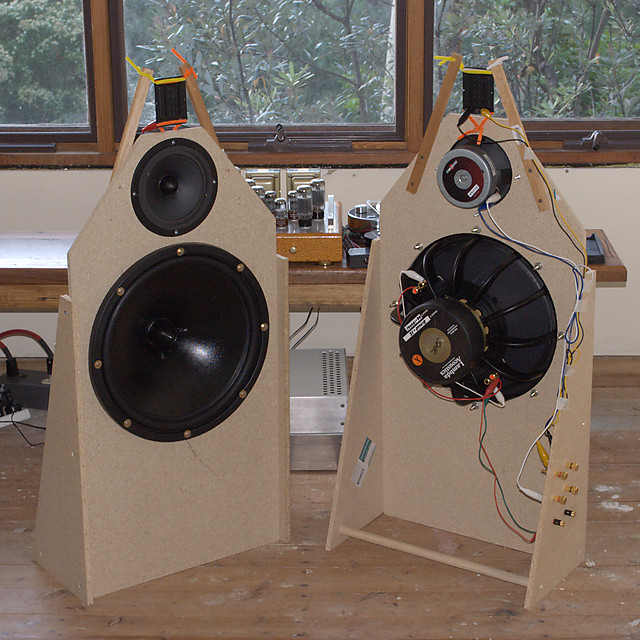
Front and rear of the prototype open baffle
As you can see: not a lot of money or effort expended on this baffle! I’ve used clip-leads to connect the binding posts to the drivers, with a few strips of masking tape to keep things tidy and reduce the chances of accidentally pulling a lead off.
Making it work
With the expensive baffle-building effort done, we can hook things up and start making some noise! Now, a professional would measure the drivers in the baffle first, but I’m a DIYer and I’m impatient. So what I’m going to do is get the project playing music first, and then I am going to progressively refine it with measurements and adjustments.
Getting connected
First, things will need to be connected electrically. The hookup for one channel is as shown in Figure 5 above. This is quite a complex configuration, so proceed slowly and carefully. Check and double-check each connection as you make it.
The BG Neo3 tweeter seems to be quite robust, and I am driving it with a tube amp anyway, so I didn’t bother putting a DC protection capacitor in series with it. If, however, you are using solid-state amps and your tweeter is less robust (e.g. a ribbon tweeter) and/or more expen$ive, then prudence suggests that you use a protection capacitor.
A word about the miniDSP power supply. The two miniDSPs can be powered from USB, or from an external DC supply. I would recommend using an external DC supply for a project using multiple miniDSPs, as you will need to unplug the USB connector when you switch the USB connection between units. Wire up the two DC power jacks as shown in this photo:
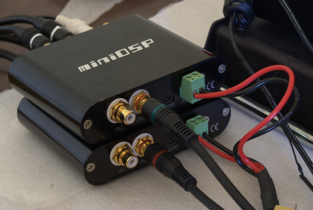
Power supply wiring for two miniDSP 2×4 units
I use a linear power supply, and off-the-shelf units are now available quite cheaply from large online electronics vendors. You can of course also build your own. In a pinch, you can use something like an old laptop charger – as long as the voltage is between 5 and 24 V DC.
If you do use USB power, then you will need a USB charger to power one miniDSP, while the other is powered from the USB connection to your computer. Be warned that in that case you will have to power down all of your amps each time you swap channels. (This is not necessary when using external DC power.)
Connecting to the miniDSP
The next thing to do is load the miniDSP configuration. After purchasing, downloading, and installing the 4-way PEQ plugin, double-click on it to run it. You will get the 4-way PEQ main screen:
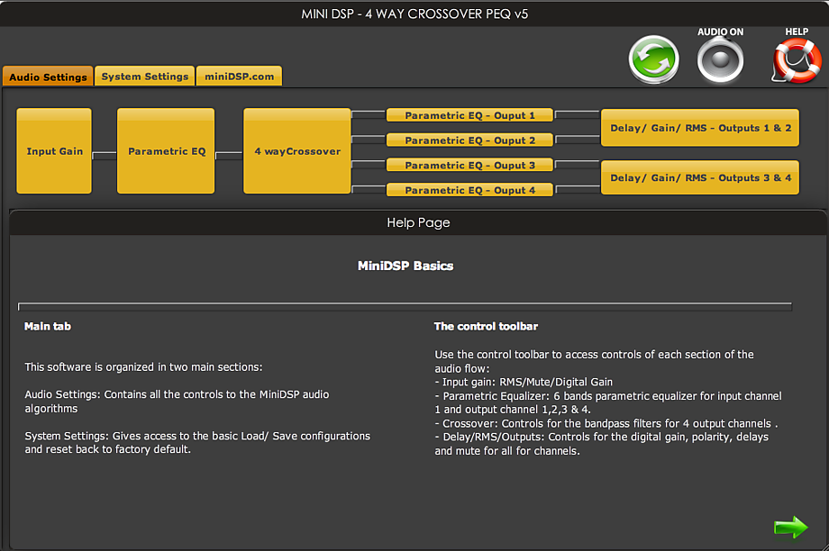
miniDSP 4-way PEQ plugin startup screen
(Click on the image to view a larger version.)
At the top is the “block diagram” showing the processing steps that the miniDSP will execute: input gain, parametric EQ, crossover, and so on. Each of these blocks is clickable, so clicking on any of them will show the parameters that you can set for that block, in the lower region of the screen.
Connect a USB cable from your computer to one of the miniDSP units. If you are using an external power supply, then you should make sure at this point that it is turned on. For now, leave all of your amplifiers turned off. Note that the USB connection is only required while configuring the miniDSP – once the settings have been finalized, there is no need for a computer/USB connection.
Then, click on the Sync button (the green one with two arrows, near the top right). You will see this dialog:
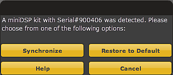
miniDSP synchronization dialog
Click on “Restore to Default.” A progress screen will display, followed (hopefully) by the success confirmation dialog:

miniDSP success confirmation dialog
(If the miniDSP is unable to connect, check your USB cabling and try again. Restarting the plugin may help.)
At this point, any changes you make on the screen of your computer will be downloaded straightaway to the miniDSP. Once we get a little further, you will be able to make changes on your screen and hear the effect immediately.
Initial crossover configuration
Now, we need to set up the crossover points. Click on the “4 way Crossover” block in the block diagram. The following screen will display (from now on the screenshots will only show the relevant part of the window, not the whole window):
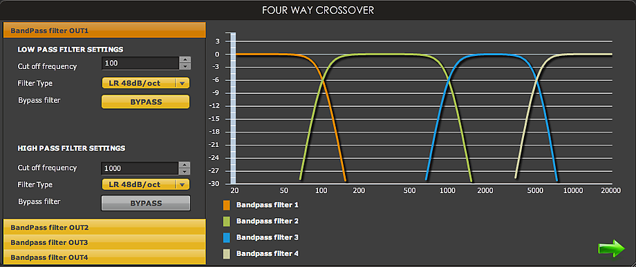
miniDSP 4-way crossover default settings
The “crossover” is really just a set of eight filters – a highpass filter and a lowpass filter for each output channel. For each filter, you can select the type of filter (Butterworth or Linkwitz-Riley) and the slope (from 6 to 48 dB/octave). Or, the filter can be turned off with the “Bypass” button. Shown above at the left are the default settings for output channel one: a Linkwitz-Riley 48 dB/octave lowpass filter at 100 Hz, and no highpass filter (you can tell because the “Bypass” button is grayed out). At the right of the screen are four curves showing the filter response of the four output channels.
You may like to experiment with the filter settings for channel 1. For example, set the lowpass filter to 200 Hz, Butterworth, 6 dB/octave. You will see the curves over on the right change. Experiment with the different settings to see the effect in the curves on the right-hand side.
You can also try setting filter parameters for the other channels. To get to the parameters for each channel click on the “Bandpass filter OUTx” button over on the left (where x is 1 to 4). Note that the settings for the filters in each channel are completely independent: you can set them so that the cutoff frequency is different for the “low” vs the “high” driver. You can also set different slopes for the two drivers (for example, 12 dB/octave for the woofer and 24 dB/octave for the midrange). This allows flexibility in the crossover settings so that the combined response (of the miniDSP filters plus the response of each driver) produces the desired acoustic crossover.
Let’s now set the initial filter parameters of each output channel. Here are my settings:
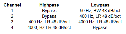
Initial crossover settings
And here is how my crossover screen looks with these settings:
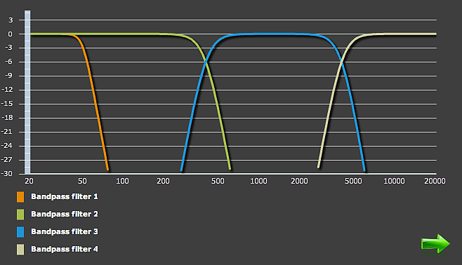
Initial 4-way crossover settings
At this point, you should save this configuration to your computer. This ensures that you can get it back anytime. Click on the System Settings tab, press the Save button, and enter the name of a file, such as “Initial 4-way crossover.xml” (the .xml extension is needed). Then press Save.
The other side
Now, we need to configure the miniDSP for the other channel. Unplug the USB cable from the miniDSP and plug it into the other miniDSP. You will get a screen warning that the connection to the miniDSP has been lost; click “OK.”
Then, to load the configuration into the second miniDSP, click on the Sync button. This time, select the “Synchronize” button on the dialog box. If the connection is successful, the settings you made above will now be loaded into the second miniDSP.
The smoke test
Let’s confirm that we have we have this set up correctly so far! You will need to connect a signal source to the miniDSP inputs if you haven’t already. I use a USB DAC and drive it from iTunes, as it’s easy to select different “test” tracks and change the volume.
First, play some music (all amps are still turned off). Click on the Input Gain block, turn up the volume a bit, and you should see the level meter bounce around a little. So far so good. Turn the volume back down. Now we are going to turns on the amps one at a time and check that we getting what we expect from each in turn.
Start with the subwoofers. Turn on the subwoofer amplifier/s and gradually increase the volume. You will of course want to be playing something with deep bass in it. Getting a bit of thud-thud there? Good. If you like, click on the “Delay/Gain/RMS – Outputs 1 & 2” block, and you should see the level meter for channel 1 bouncing around a little. Turn down the volume and turn off the subwoofer amps.
Then repeat the above with each of the other channels. Do be careful with the tweeters. Don’t, for example, crank up the volume just to get the level meter to show something – that’s a good way to damage a driver and possibly your hearing as well. In each case, check that the drivers in both speakers are operating and sound roughly the same. That doesn’t mean putting your ear right up to the driver – protect your hearing please!
If that’s all been successful, you can turn all the amps on and play some music. It probably won’t sound good – at this point, we haven’t matched the driver levels, which is the next step.
Making it right
We now need to adjust the levels of the drivers and perform some basic equalization. For the rest of this article, I am going to forget about the subwoofers and focus on the main (3-way) panel. We will integrate the subs after we know more about how well the main panel performs at low frequencies.
Level adjustments are impossible to do by ear – some form of acoustic measurement capability is essential. I described a basic in-room measurement setup in the previous tutorial, so please refer back there if you don’t yet have any measurement capability.
For now, I’m going to do this level adjustment using an in-room measurement. This is not optimum, but it’s a reasonable way to make some progress at this point. The measurements are being done in a fairly small room (my study), so will look a little different in a more realistic room (for an open-baffle speaker). I think this is OK: we are just getting going, and the speakers will be moved to a larger room after more sophisticated measurements are done.
Initial level adjustment
To perform an initial level adjustment for the three amp/driver channels of the main baffle, I placed the microphone about a meter from the right speaker, in line with the midrange driver. This is far enough that we can get all drivers in well enough, without being totally swamped by room effects.
I disconnected the input signal from the miniDSP that is driving the left channel. (I’m assuming that the right miniDSP is the one that is still connected to the computer by USB.) What we’re looking for here is an abrupt level change at the crossover points, indicating mismatched sensitivities of the corresponding amplifier and driver channel – 1/12-octave smoothing seems to work well for this purpose. So here is the initial measurement sweep with 1/12-octave smoothing:
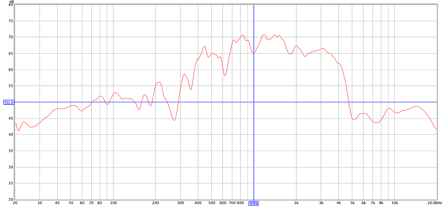
Figure 9. Initial sweep with no correction
Remembering that the crossover points are 400 and 4000 Hz, it’s obvious from the plot above that the main issue here is that the midrange driver is way too loud. The degree by which this is so surprised me, until I remembered that the overall sensitivity is a function of the gain of the amplifier in use on that channel as well as the driver.
There are a number of ways to address the gain discrepancy, but for now, let’s use the output gain control provided by the miniDSP. The midrange driver is output channel 3, so click on the “Delay/Gain/RMS – Outputs 3 & 4” block, and set the output gain control for channel 3. Here it is set to -18 dB:
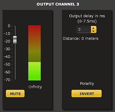
Midrange attenuation
Here is the subsequent measurement sweep (in blue, with the original in red):
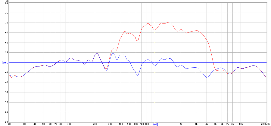
Figure 10. After midrange level adjustment
Much better. Note that, for an in-room measurement, we’re not looking for a completely flat response, but one that slopes down gradually.
Simple response corrections
There are some further simple adjustments we can make at this point. From the plot above, we can see that the woofer is starting to roll off below around 80 Hz. To correct for this, we will use what is known as a shelving filter – so-called because it puts a “shelf” in the frequency response. Click on the “Parametric EQ – Output 2” block to bring up the following adjustment screen (click to enlarge):
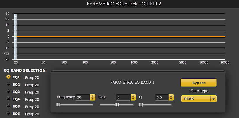
miniDSP default parametric equalizer screen
We want to boost the woofer output by about 4 dB at 60 Hz. So set Gain to 4, and the Filter Type to “LOW-SHELF”. The two other parameters are the centre frequency of the boost, and the “Q,” which controls its steepness. You will need to experiment a bit with these, but here are the values I’ve chosen:
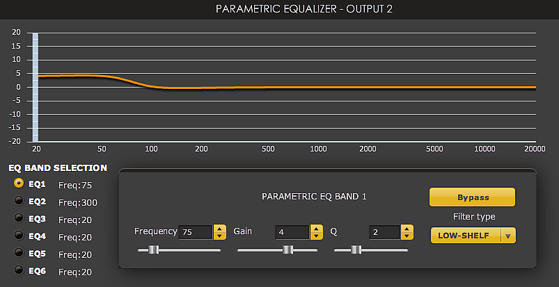
Woofer shelving filter
The new result is shown here in green:
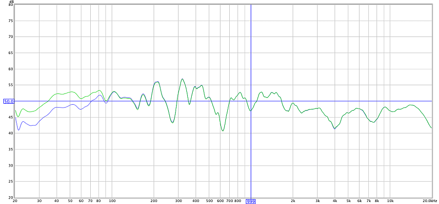
Figure 11. After woofer shelving EQ
The speaker now looks pretty much flat to below 40 Hz. It’s a bit rough in the midrange, but with this type of measurement we can’t tell if it’s the speaker doing that, or reflections from the walls and floor. So let’s leave that alone for now.
I did, however, wonder about the dip at 4 kHz, which is the crossover point. After experimenting with EQ and changing the crossover point, I realized that the tweeter was out of phase with the midrange. My tweeter amp must be inverting phase. This is something to look into (i.e. why is this amp inverting phase?), but for now, I’m simply going to invert the tweeter output signal using the miniDSP.
To do so, click on the block “Delay/Gain/RMS – Outputs 3 & 4” and then click the “Invert” button for channel 4. It will grey out, indicating that the tweeter output is inverted:
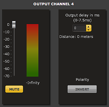
Inverting the tweeter output
Running another sweep verifies that this has corrected the problem around the crossover region (new plot in purple):
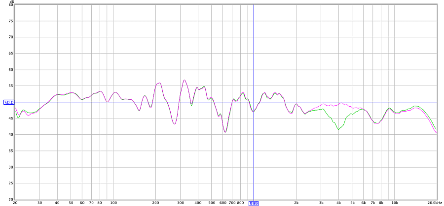
Figure 12. After tweeter phase reversal
As far as driver integration goes, we’ve now reached the limits of what we can do with in-room measurements. In Part 2 of this tutorial, I will redo the driver integration with more finesse, using gated measurements.
In the meantime, let’s check the response at the listening position:
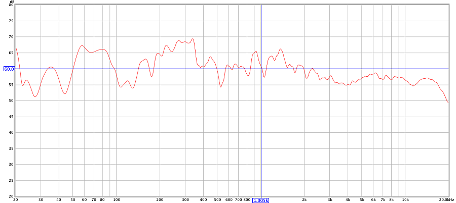
Figure 13. In-room measurement at the listening position
Oops. Even though the speaker is in a temporary location, I decided to do a little more EQ to even out the worst of the room anomalies. On the woofer, I added a high-shelf filter, to bring down the response above 200 Hz, and a broad notch to bring down the response in the 50-90 Hz region (see the first tutorial for information on how to do this). Here is that notch and the resulting equalization curve of the woofer:
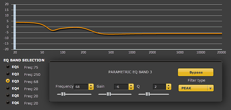
Woofer equalization curve
I also added a broad notch to the midrange driver to bring down the response in the 900-1300 Hz region (where it looks to me that the dipole peak is appearing in this measurement – we will find out in Part 2!). The measurement at the listening position after these adjustments is:
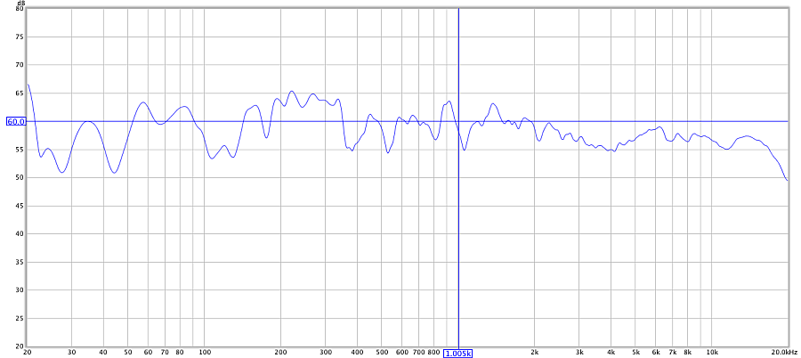
Figure 14. In-room measurement after further equalization
Not too bad for a first go around and a few hours of work! At this point, save the configuration to another file, called say “4-way after basic eq.xml” (note extension).
Do the other side
We’ve only done one channel at this point! Swap the USB connector to the other miniDSP and synchronize again. You may wish to run a measurement sweep on that channel to make sure that you’re getting what you expect.
Note: I strongly recommend against powering a miniDSP up or down while your amplifiers are turned on. So, if you are using USB power, please make sure that you turn all of your amplifiers off before unplugging the USB cable, and turn them on again after re-synchronizing. (If you are using an external DC power supply, this is not necessary – you can simply unplug the USB cable from one miniDSP and connect it to the other.)
Once you are satisfied – and if you are using an external DC power supply – you can remove the USB connection, as there is no need to leave the computer connected to the miniDSP for normal operation.
Wrapping up Part 1
At this point, we have the main 3-way baffle running and playing music. Listening to it, there are some issues that are not apparent in the simple measurements that we have done so far. But we’ve only just started!
With your own project, as you listen more, you may wish to make some more adjustments to the levels or equalization we have looked at so far. Just remember that you have to do both channels, and that it’s a good idea to save the configuration to a new file each time you get to a point that you like. If you are feeling adventurous, cross in the subs and see how well that works out. For my part, I am going to let the drivers run in for a couple of weeks and then start with some more advanced measurements for the next part of this tutorial.
Acknowledgements
My sincere thanks to those who commented on this article and helped to improve it, in particular Michael Mardis, Tony Rouget (of miniDSP), and Randy Kunin.


John:
I am grateful to have found your site here and these DIY pages you have written.
1. Your work is really honest. It’s tough being a guy sometimes. We’re supposed to know everything and never admit “weakness” (whatever that means). On a lot sites you are basically punished for posting questions showing any lack of experience/knowledge in some area.
You turn that on its head here, acknowledgint that everyone has to start somewhere.
2. Your writing is SUPERB. Really. I used to edit papers for a living, at one point. I worked in IT, read tons of awful documentation, and I taught IT subjects at a local college. I know good writing when I (rarely) see it. You are a natural born writer. I originally came here to read over your pages on the MiniDSP, but I started reading your section about dipoles and…well…I just have to get some sleep, but will be back again…to read…whatever else related that you write, because I know I will learn something.
John, if you think I’m flattering you, well…I guess I am. I’m hoping I may be able to come to you at some point and compare notes or ask advice. I bit off more than I can chew by buying some sweet 10″ fiberglass woofers and a router for cutting and a circle guide and now…realize I have little idea what I’m doing. Whoops.
Now, if only the MiniDSPs included some type of interface so that you didn’t have to use an external computer. Something like a touchscreen. I wonder how much that would cost to implement…
I hope to God that you consider writing a book at some point. If you do, I’ll be first in line to buy it. Again, thanks for your work here.
Hi Brad, thank you for your kind comments, much appreciated! With regard to those 10″ woofers, there’s only one thing to do with them and that is to mount them into a baffle and see how they go. Measurements and EQ would of course be my recommendation but in the end the key point is to make some progress and learn something along the way.
Hi,
Very informative article and it filled in some of the practical questions you
usually only get to when you have the boxes in hand.
I have a DIY 5 way horn system, 3 x 12 sided conicals tapped horns and horn tweeters, crossing at 90 / 330 / 1250 / 8000. Currently I have
a passive 2nd order 12dB crossovers (big inductors 24mH and big
polyprop caps) on the lower crossovers.
It sounds very good as is and is nearly there.
Sub is a tapped horn and these really needs to EQ and steeper eg 3rd or 4th order crossovers
really. Hence my thinking about miniDSP.
I am prepared for 5 amps too.
I would probably go for the 8×8 kit the extra sampling and bit rate is good.
Thanks again for the article.
BR
Steve
4-way open baffle would require cascaded filter stages using biquad filters.
Otherwise the lowpass of the previous stage would influence highpass of the next stage.
This is because the cutoff frequency is *not* far enough as opposed to 3-way.
Hi gainphile, that is true in the sense of a “textbook” filter design, but in practice using the parallel topology for a 4-way doesn’t seem to cause significant problems. I suspect that any anomalies caused by the phase shift “leak” get taken care of when adjusting the gain of each driver and fine-tuning of the equalization filters – in particular the dipole compensation shelving filter which each driver has already. Doing a cascaded topology in DSP would require a lot of extra biquads (if I understand correctly). So you wouldn’t be able to do steep slopes in that case…. trade-offs!
It may be interesting to try some day though, thank you for reminding me of it. Is it something that you have done in your system?
Looking at my response plots again, there is an issue of some kind at the mid-tweeter crossover. The dispersion pattern changes there as well, so it may well be a phase-related issue. I’d say it’s relatively minor.
Hi.
Interesting read, though
what I’d do different is
1. that I’d adjust first the time and phase of the drivers before adjusting the levels.
That gives you a much better starting point with the driver level adjustments.
2. instead of adjusting your midrange driver digitally by -18db, I’d add a passive attenuator or I’d buy
better matching drivers.
Cheers
Hi Klaus, thanks for the comment. Those are both done in Part 2 (link near start of article).
So glad I found your article! I just heard the Nightengale Concentus open baffle speakers at Axpona 2013 and started thinking a clone could be a realistic diy project. On the other hand, I’m skeptical of being able to get all of the subtleties down as well as the real thing. I’m hoping that DSP will be able to bridge the gap in real-world performance since I don’t have a team of audio engineers working on my design. My design will probably track their driver usage as closely as I can determine. Dave
Hi John. Wht’s the advantage of sound being produced from 4 way over 3 way ? Most of modern good quality loudspeaker can produce tight flat +- 5 dB across audio freq, 20 Hz-20 kHz with 3 way system. Would you mind to reply your answer to my eml please as I’m not sure if you answer through this forum my email would alarmed me. Thank you.
HI Jonaton, because of the dipole rolloff (see “theory” section in article above), the frequency range of the larger drivers tends to be more limited than when used in boxes. I suppose I should really say “three-way plus sub/s” – in terms of the active crossover needed, it’s (almost) the same. A three-way or two-way open baffle speaker is more demanding on the individual drivers.
John great article. I’m working the exact same project with my ,,Emerald Physics 2.4 3 way open baffle design and the miniDSP 4x10hd. Because the drivers are 97db/watt I hear everything . So I have a gain problem . I don’t know how to get the gain noise problem solved . I m using a DSPeaker I front of the miniDSP for my preamp. The quiet passages are not so quite ,full of hissing noise .
Do you recommend a blocking cap on tweeters given the danger of damage ?
Thanks for your advice Carl
Hi Sir! Cool setup! I’m planing a similar my self.
Have you tried ab testing 24dB – 48dB cross points concerning “natural sounding” sum. 24db is standard on all Pro live concerts. I wonder a bit why .. worth a test! Cheers!
Hi Niclas, I suspect that the reason why 24 dB/octave is “standard” is because that is the optimum configuration for analog implementation. I am for myself moving to linear phase DSP crossovers. More on that when I get my revised version of this project a little further developed 😉
Did you get to linear-phase yet?
Hi Per, yes, I am currently running my next version with linear phase crossovers.