Mini Convertible: Crossover
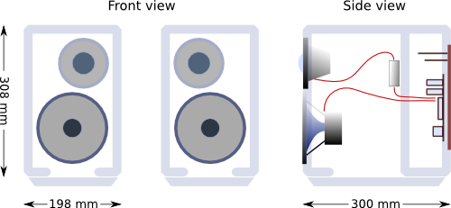
In my first article on the Mini Convertible active loudspeaker using the miniDSP PWR-ICE125 plate amp and drivers from Seas, I gave the rationale for the particular choice of drivers and showed some measurements of a preliminary crossover design. In this article, I’ll work through the crossover design more carefully and explain the steps along the way. First, though, there have been a couple of changes to the speaker:
- The tweeter is now offset horizontally with respect to the woofer, by 19 mm. I built a prototype baffle with such an offset tweeter to see if this layout reduced the effects of diffraction from the edges of the baffle. It did, so I’ve switched to that baffle now.
- I’ve placed a capacitor in series with the tweeter. While I’ve had no issues with the tweeter directly connected to the amp output, the capacitor does help reduce the low-end rise caused by the waveguide, improves signal-to-noise ratio below the f3 (which might be helpful if the speaker were used nearfield, say on a desk), and greatly reduces the chances of damaging the tweeter during measurement sweeps.
Terms of use
This design is released under the Creative Commons Attribution license. That means, in a nutshell, that you can use it and modify it as you like, including commercial use of the design, provided that you provide attribution to the original source with this link: https://www.hifizine.com/issues/mini-convertible.
Outline of the design process
This is the block diagram of a typical DSP-based active crossover:
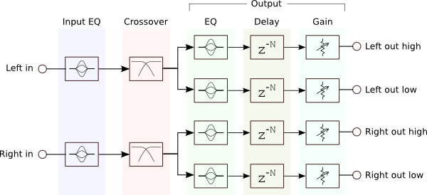
In this article, I won’t be using any advanced design software – just measure, make an adjustment, and remeasure. The procedure I will use is as follows:
Flatten driver response. The Output EQ block is used to flatten the on-axis response of the respective driver. Ideally, the final response of the driver should be flat a good amount past the crossover frequency, where “good amount” is ideally three octaves, although in practice I’ve found that you can get away with an octave.
Apply baffle step compensation. This is a shelving filter to compensate for the “baffle step loss” caused by the transition of the acoustic wave from half space to full space, typically at a few hundred Hz. This is done as part of flattening the woofer response, and is best done in the Input EQ block (*).
Implement the crossover. Since each driver now resembles a “perfect” driver, start by matching the gains of the two drivers in Output Gain, and then apply a “textbook” crossover filter in Crossover. Some adjustment and tweaking will most likely be needed, the largest part of which is adjusting the Output Delay on one of the drivers so that the drivers have the correct phase relationship at the crossover point.
Perform complete measurements. With the first pass at the crossover now done based on the on-axis measurement, the results should be verified with a set of off-axis measurements. This may lead to some additional adjustment and tweaking.
(*) While the baffle-step compensation (BSC) can be done in the Output EQ for the woofer, the amount of BSC desired can vary with speaker positioning (as much as 6 dB if the speaker is well out into a good-sized room, or as little as 2 dB or maybe even none if backed up against a wall). Putting BSC into the Input EQ allows this adjustment to be made more easily.
Tweeter equalization
With the tweeter offset on the baffle, the on-axis measurement is improved over the first prototype, where I optimized the speaker for a slightly off-axis response. So this time, I’m going to use the on-axis measurement to optimize the speaker.
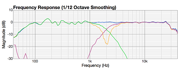
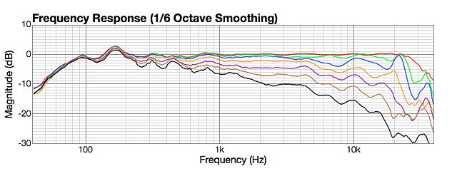
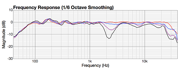
First, let’s see the effect of inserting the capacitor inline with the waveguide tweeter (Seas 27TBCD/GB-DXT). The capacitor is a 5.6 uF film type, calculated to provide a high pass roll-off at 5 to 6 kHz. This graph shows the tweeter with no capacitor in orange, and with the capacitor in series in red:
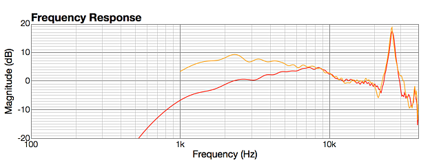
You can see that the tweeter is attenuated about 9 dB at the 2 kHz crossover point, bringing it down to roughly the same sensitivity as above 12 kHz. (The reason that the measurements are different at high frequencies is, I think, because the orange one was taken at a distance of 0.5 m, while the red one was taken at 1 m. It makes no substantive difference to what the graph is intended to show.)
Since the amp runs at 96 kHz, I decided to also run the measurements at that rate, hence the graph displaying out to 40 kHz. (The measurement microphone is calibrated to 35 kHz.) Although not strictly necessary, I find it interesting to see what’s going on beyond the nominal range of audibility. The graph shows that the tweeter has a strong resonant peak from the hard dome at 26.5 kHz.
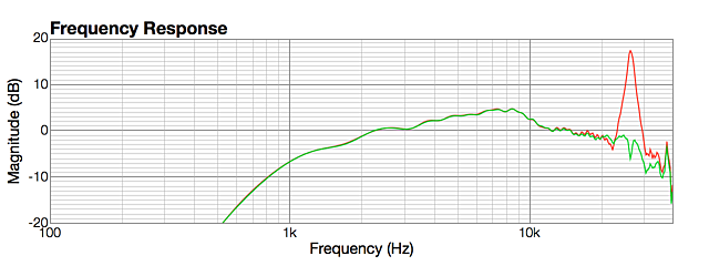
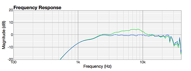
This is presumably completely inaudible, but I decided as an exercise to try flattening the peak anyway. Since the “basic” mode of the miniDSP parametric EQ only goes up to 20 kHz, I switched to “advanced” mode and used the biquad calculator spreadsheet. Two filters were needed, resulting in the measurement shown in green:
Three more bands of parametric EQ are enough to flatten the tweeter’s on-axis response in the audible range (in blue):
The tweeter now starts rolling off around the chosen crossover frequency. To flatten the response further and help linearize the phase, a shelving filter was used to bring up the response at the low end, as shown here in purple:
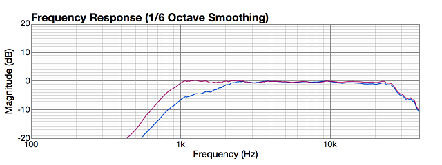
While caution should always be used when boosting the low end of a tweeter, the series capacitor greatly reduces the risk of over-driving the tweeter. Note that once the crossover is in place, there will actually be no boost in the signal fed to the tweeter – the effect is only to linearize the crossover response.
Woofer equalization
Equalizing the woofer (Seas U16RCY/P) is a similar process. But first, we need to set up a BSC filter with the Input EQ block. We can get a good idea of where to do this by using a simulator such as The Edge. This is the response that The Edge shows when modeling the woofer in the Mini Convertible baffle:
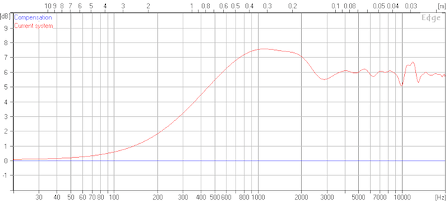
Edge baffle step for Mini Convertible
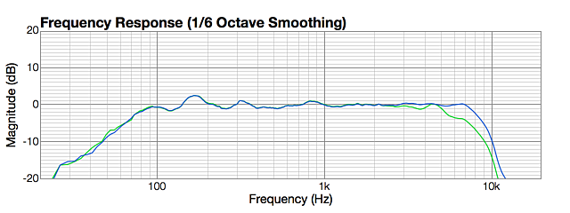
The halfway point (3 dB) for the baffle step loss is at 300 Hz, so a shelving filter centred at 300 Hz can be added to the Input EQ. Below is the measured response of the woofer in the box in red, and with baffle-step compensation in green. I used 5 dB instead of 6 dB as that gave the flattest result. (Note that, while these measurements are taken outdoors, there are still some reflections that affect the response below 1 kHz.)
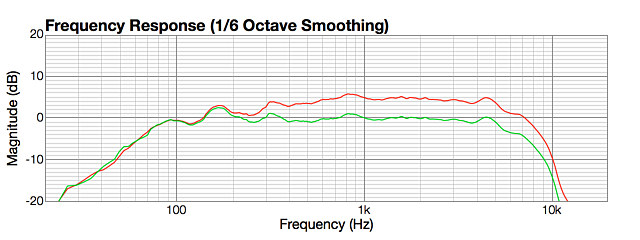
A few additional corrections extend the woofer’s response well past the crossover frequency (in blue):
Crossover and integration
Finally! The crossover. In theory, flattening the response a good amount on either side of the crossover frequency also flattened the phase, making implementing the crossover easy. In practice, some adjustment is needed, the main part of which is aligning the phase at the crossover frequency. Here’s a simple empirical method to do this:
- Adjust the level of one driver or the other so that they are equal in their passband.
- Put a Linkwitz-Riley fourth-order filter on both drivers at the crossover frequency.
- Invert the tweeter, and measure the response.
- Adjust the delay (usually on the tweeter) in small increments until you obtain the deepest null you can at the crossover frequency.
- Set the tweeter back to non-inverted.
With that done, the combined response should be close to flat. Some small further adjustments to the overall response may be desired, which can be done in the Input EQ block.
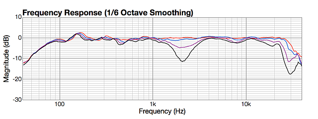
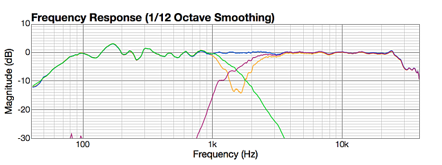
Using the above procedure and with the mid-way point between the woofer and tweeter as the design axis, I ended up with 0.13 ms delay on the tweeter. Here is the response with the inverted tweeter in orange, the final adjusted response in blue, and the individual responses of the woofer and tweeter in purple and green (note: graph runs from 40 Hz to 40 kHz):
Driver and summed responses, Linkwitz-Riley 4th order at 2000 Hz
I covered the topic of off-axis measurements in the earlier article, so here I’ll simply summarize the full results provided in Appendix A. The horizontal off-axis measurements confirm the initial results and show a gradual and smooth drop with angle and frequency. The dispersion pattern is well controlled although with wider dispersion than seen in speakers with larger waveguides. There is a broadening in dispersion around 10 kHz, so this waveguide is not “perfect.”
Vertically, the measurements are also very good, with a slight dip at the crossover frequency at +/- 15 degrees off axis, becoming more apparent at +/- 30 degrees. This is an inevitable consequence of the spacing between the two drivers. As an experiment, I also implemented a crossover at 1500 Hz to see how the vertical measurements improved – these are presented in Appendix B.
Concluding remarks
The Mini Convertible has now had a more careful crossover design and a more complete set of measurements, which confirm that the speaker gives a wide but well-controlled dispersion. The wide dispersion does mean plenty of in-room treble energy, which may in some circumstances not be desired. While the speaker rolls off around 80 Hz and so is obviously intended for use with a subwoofer, don’t even try and get away without one as the speakers can easily sound thin if used without. A competent subwoofer is a must.
Looking at the graphs as I’ve been writing the article, I wonder if the crossover could perhaps be tweaked slightly with a small boost to the 400-700 Hz region. The response could also be tweaked for a smoother response at any chosen off-axis angle, if desired. I don’t think there is much else that could be done, other than perhaps try a completely different type of crossover – something for a future article, perhaps.
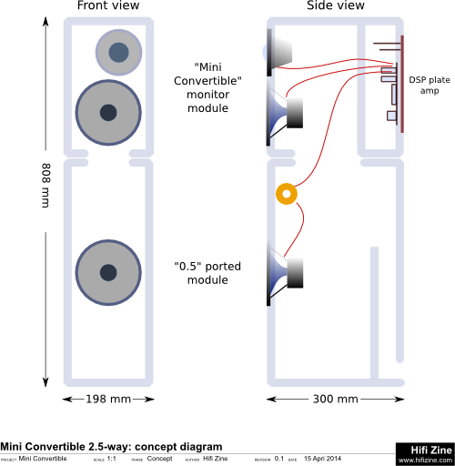
I also hope to (eventually) build the ported base. I’m thinking that instead of a simple ported base as planned earlier, I will make a “0.5” base, like this:
Finally, here is the configuration file for the crossover:
Acknowledgements
HifiZine gratefully acknowledges the support of the following companies and individuals:
- miniDSP, for providing the amplifiers used in this loudspeaker project.
- Seas of Norway, for providing the loudspeaker drivers used in this project.
- SuperMegaUltraGroovy for the use of their excellent FuzzMeasure Pro 3 measurement program.
- Paul Spencer (Red Spade Audio) and Chris McKeague for reviewing and commenting on this article.
Appendix A: Off-axis measurements
This appendix contains the off-axis measurements for the 2 kHz Linkwitz-Riley crossover. Note that the graphs are from 40 Hz to 40 kHz. These measurements were performed outdoors but there are still some reflections affecting the measurements below 1000 Hz. These should be ignored, and the trend between curves focussed on.
Horizontal off-axis measurements
The horizontal off-axis curves were measured for both “sides” of the speaker – the side closest to the tweeter, and the side farthest from the tweeter. I had expected the “tweeter side” to give better results than the “far side,” but that doesn’t seem to be the case, with the tweeter side showing a slight droop between 1-2 kHz that is less evident in the far side curves.
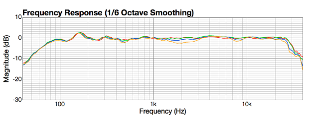
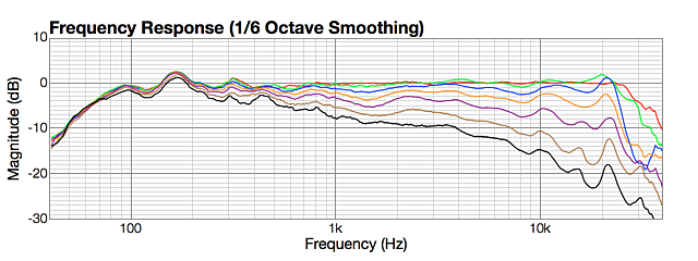
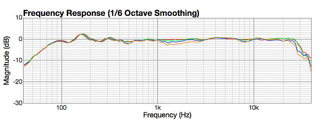
This is the set of tweeter side measurements, in 15 degree increments from 0 to 90 degrees:
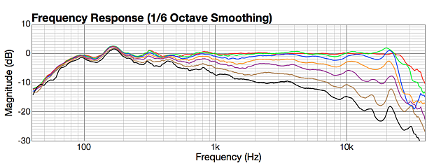
Horizontal off axis, LR4 2000 Hz, tweeter side – 0, 15, 30, 45, 60, 75, 90 degrees
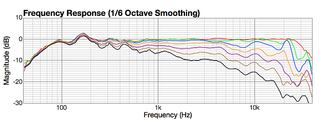
This is the side farthest from the tweeter:
Horizontal off axis, LR4 2000 Hz, far side – 0, 15, 30, 45, 60, 75, 90 degrees
Vertical off-axis measurements
Every crossover with drivers spaced apart vertically will exhibit lobing in the vertical direction – in other words, the off-axis frequency response will have a dip in it near the crossover frequency. The exact nature of the lobing depends on the type of crossover, driver spacing, and crossover frequency. Here, the dip is just visible by the time the microphone moves 15 degrees off axis, and is quite obvious 30 degrees off axis. The curves are fairly symmetrical up and down, as you would expect for a Linkwitz-Riley crossover.
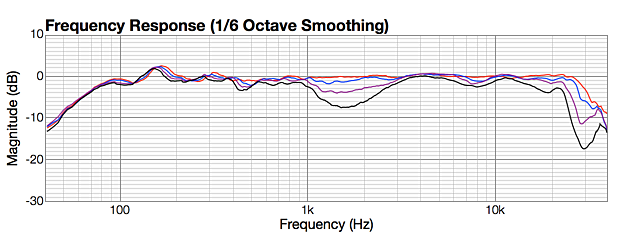
Vertical off axis, LR4 2000 Hz, up 0, 5, 10, 15 degrees
Vertical off axis, LR4 2000 Hz, up 0, 10, 20, 30 degrees
Vertical off axis, LR4 2000 Hz, down 0, 5, 10, 15 degrees
Vertical off axis, LR4 2000 Hz, down 0, 10, 20, 30 degrees
Appendix B: Fourth-order Linkwitz-Riley crossover at 1500 Hz
I decided to also try a crossover at 1500 Hz, to see if vertical dispersion could be improved even further. While not part of the main article, I’ve included it in this appendix as there may be a few people interested in the results. While 1500 Hz seems low, distortion measurements indicated that the tweeter was not bothered – it might be an issue in a speaker designed for higher output, but in this speaker the woofer will give way well before the tweeter shows signs of strain.
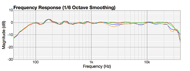
Here are the on-axis response curves:
Driver and summed responses, Linkwitz-Riley 4th order at 1500 Hz
Following are the various off-axis response curves and the listening window response.
Horizontal off-axis measurements
The horizontal off-axis curves are very similar to the 2 kHz curves:
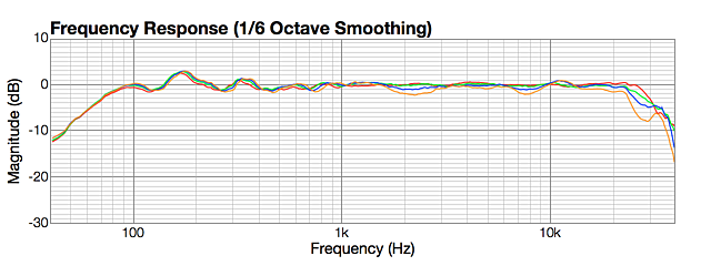
Horizontal off axis, LR4 1500 Hz, tweeter side – 0, 15, 30, 45, 60, 75, 90 degrees
Horizontal off axis, LR4 1500 Hz, far side – 0, 15, 30, 45, 60, 75, 90 degrees
Vertical off-axis measurements
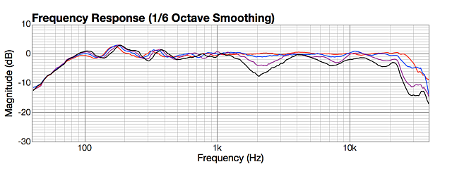
Compared to the curves for the 2 kHz crossover, it can be seen that there is a reduction in the depth of the off-axis dip at all angles, but especially visible at the +/-30 degree angles. Note, however, that +/-30 degrees is a large vertical window – typically +/-10 or +/- 15 degrees is considered to be the “listening window.”
Vertical off axis, LR4 1500 Hz, up 0, 5, 10, 15 degrees
Vertical off axis, LR4 1500 Hz, up 0, 10, 20, 30 degrees
Vertical off axis, LR4 1500 Hz, down 0, 5, 10, 15 degrees
Vertical off axis, LR4 1500 Hz, down 0, 10, 20, 30 degrees


John,
I have the PWR-ICE125 plate amp and have been very happy with it. I tried opening up your crossover design to get an idea of how you approached your crossover design, but a received this message:
The system settings configurations are most likely incompatible or do not exist. Please load
Do you have any thoughts on what I need to do to overcome this? BTW, I think your mini convertible design is a nice one!
v/r
Milan
Hi Milan, thanks for your comments. There was a firmware update to the PWR-ICE a little while back, I suspect the reason for the error is that I’ve been using the new one and you have the old one in your amps? As I recall the new firmware comes with the new 2×2 plugin (download from User Downloads on minidsp.com). Unfortunately if you update to this new firmware/plugin you have to re-enter all your settings by hand, as there’s no automatic update/migrate of existing data.
Ah, OK. I thought I had the updated firmware, but I will confirm and make sure I have all of my existing settings written down.
Thank you very much for taking the time to write and publish this! I have always wanted to build active speakers and have finally decided to begin, and this information has been extremely helpful. I just ordered my mini dsp ice 250 – coming in on Friday. Going to start off with a small 2 way with a seas 12mm woofer and a Vifa ring radiator and see how things pan out,
I’m using Shahunian elf speakers and genelec 1029a’s as my reference.
Once again – thank you very much! Your description of the mini dsp being ” simplicity itself” convinced me to buy it and get started!
– Christopher Snow
Hi Christopher, thank you for your comment and I’m glad my articles helped you.
Very well executed DIY project! Oftentimes DIYers when designing their projects do not seriously occupy themselves with off-axis performance/measurements. Also I congratulate and like your approach of going fully active.
Nevertheless this project judged purely from cost/performance perspective in the presented implementation with ICEpowered minidsp plate amps makes it utterly expensive (300 EUR for drivers + 600 EUR for plate amps + cabinets etc.). IMHO an investment too large into a system of this size. There are speakers on the pro monitoring market possibly offering similar performance that can be had for less e.g. look at Yamaha HS5/HS7/HS8 monitors (using waveguide on tweeter too). But of course, to make the project more cost effective one case use cheaper/existing amplifiers and do xovers/eq purely in software and feed the amps from computer.
Hi David, thank you for your comment. I partly agree with you and partly not. The amps are much more power than really needed for the drivers, so arguably better cost/performance could be achieved with either a lower power amp or (more likely) larger drivers that offer greater SPL. However, I find the comparison with the Yamaha monitor curious – I can buy a pair of HS5 here for less than I can buy the drivers for the Mini Convertible. If your “possibly” were an “actually”, that would mean that DIY is pointless (as the benefits of mass production are such that you can get a complete speaker with enclosure and inbuilt amplifiers for less than the retail of the equivalent drivers alone). Or perhaps it’s simply the particular class of speaker (small active) where this would (might) apply.
I think the real advantage of this particular configuration (two way with the miniDSP amps) is the digital input and passthrough. You can chain the two speakers and then a subwoofer (or two). I do have a diagram of that but appear to have not put it into either article… Then you just connect a digital source (requires digital volume) – no DAC, preamp, or any other extra boxes needed. Unfortunately I don’t have a third amp with which to try this configuration out… perhaps at some point I will.
I’d be interested to learn more about the specifics of what you would suggest as a cost-effective active loudspeaker project. Or if you have a project that you’d be interested in writing up for HifiZine, please send me a note via the Contact link 🙂