The Mini Convertible active loudspeaker: design
One of the drawbacks of building active speakers is the plethora of cables and boxes that result. Somehow, they just seem to multiply. One way of dealing with this is to put the crossovers and amps into the speakers. While I’ve always preferred “separates” since I’m an inveterate tinkerer, there is definitely something to be said for the neat, self-contained approach.
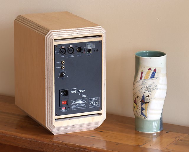
The above speaker is a prototype of a little project I’m working on using a two-way plate amp from miniDSP, which incorporates their eponymous DSP functionality together with a B&O ICEPower module. This amplifier module simplifies the electronics part of the project: instead of a separate DSP crossover with multiple amplifiers and associated wiring, a single pair of amp modules is all that’s needed.
The drivers are a perfect fit for a compact active loudspeaker and met with the design goals I had for this project. They were kindly supplied by Seas of Norway. This first article – in what I intend to be an on-going series of articles – will cover the design concept of the speaker and includes measurements of the prototype with a straightforward crossover. The next article will look into crossovers in detail, and the remaining articles will describe how the loudspeaker is constructed and explore the “convertible” aspect of the speaker.
A little theory
Imagine the perfect reproducer of sound: the point source. This source radiates sound energy equally in all directions, so no matter where you might be positioned (in front, to the side, above, behind), it would sound the same. Real speaker drivers, however, exhibit a degree of directivity as a consequence of their physical size and the fact that they are (typically) positioned on the baffle of a box. That is, the sound produced by the speaker is strongest in one particular direction – usually directly in front of the speaker or driver, referred to as on-axis – and weaker in other directions. This variation is frequency-dependent and can be shown in a number of ways; but a simple one is to show the frequency response curves at different angles relative to the on-axis position.
Figure 1 illustrates response curves of a hypothetical two-way speaker. At the top is the on-axis frequency response of the woofer in blue, and in red the off-axis response at, say, 30 degrees in the horizontal direction. At higher frequencies, the off-axis sound level drops relative to on-axis because of the woofer’s increasing directivity – the woofer is starting to “beam.” The next pair of curves are for the tweeter. Like the woofer, the off-axis output drops off as frequency increases, but at a much higher frequency. Finally, at the bottom we’ll assume that we have created a perfectly flat on-axis response with a crossover. The horizontal off-axis response shown in red, however, is not flat: because of the different off-axis outputs of the woofer and tweeter near the crossover, the combined off-axis response has a pronounced dip in the response below the crossover frequency.
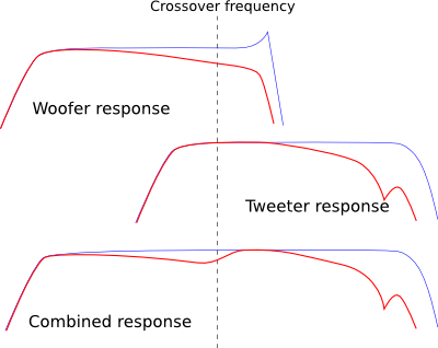
Figure 1. Typical off-axis response of a two-way loudspeaker
This is fairly typical behavior for a two-way loudspeaker, and can be seen in numerous frequency response measurements posted online. See, for example, the response plots made by the Canadian NRC of the Thiel CS1.6, Seas’ measurements of the Mimir kit, the measurements on Stereophile of the Proac Response Two, and so on. (See also this explanation from Stereophile). This is not to criticise those loudspeakers, but to point out that it’s a common trade-off made for a two-way loudspeaker.
Why would we care how a speaker measures anywhere but on-axis (assuming that the speaker is pointed at the listener)? Because what you hear when you listen to a speaker in a room is not just the direct sound from the speaker, but also the sound created by reflections within the room. In Chapter 18 of Sound Reproduction: The Acoustics and Psychoacoustics of Loudspeakers and Rooms, Floyd Toole explains that in blind listening tests the quality rating of a loudspeaker is strongly correlated to three factors:
- Flat on-axis response
- Smoothly-varying power response
- Lower -10 dB extension frequency
The power response is the acoustic output of the loudspeaker integrated over a sphere with the speaker at its center. That is, it is the frequency response of the total sound radiated into the room, regardless of direction. (See Note 1 below.) And a smooth horizontal off-axis response is a significant factor in achieving a smooth power response. If, as illustrated in Figure 2 below, the dispersion (see Note 2 below) of the tweeter at the lower end of its range is deliberately limited so that its off-axis response is reduced at the crossover frequency, the off-axis response through the crossover region is now smoothly decreasing. (As an aside: a benefit of controlling tweeter directivity is that the off-axis response at the high end is often smoother as well.)
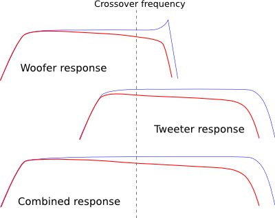
Figure 2. Off-axis response of a two-way loudspeaker with controlled directivity
There are other design factors that affect the power response. One is the need for baffle-step compensation for a small speaker (with typical in-room placement). Another is the fact that the two drivers will create vertical lobing around the crossover region. (See Note 3 below.) The nature of this lobing depends on the specifics of the crossover.
Driver selection
I decided early on that I wanted controlled directivity – as described above – to be a design goal of the Mini Convertible. One approach, exemplified by the Econowave family of DIY speakers, uses a compression driver combined with a horn or waveguide to limit tweeter dispersion throughout its range, typically to a 90 degree arc (measured at the -6 dB points). A fairly large (12″ or 15″) woofer is used so that its dispersion narrows to 90 degrees to match the tweeter at the crossover frequency. This is also the approach taken in Duke LeJeune’s Controlled-Pattern Offset Bipole.
In this project, I’ve taken a different route, choosing a tweeter that has relatively wide but still controlled dispersion, and a woofer that is small enough to match this tweeter at the crossover. This enables the speaker to meet the goal of smoothly-varying power response, but in a very compact size. The tweeter had to be an off-the-shelf unit – something like the custom-machined waveguide used in the Vapor Audio Aurora, for example, would not be feasible for a DIY project. There are not very many suitable candidates, but fortunately Seas of Norway makes one, the 27TBCD/GB-DXT, readily available at a very reasonable price.
Choosing a woofer is very much a matter of choosing amongst compromises. There are a vast array of choices not just in woofer size but also related to cone material, frequency response, sensitivity/low-end trade-offs, the woofer parameters that govern the type of box possible, and of course cost and quality. As a very general rule, smaller woofers have lower sensitivity, less low bass, and lower maximum output than larger woofers, but larger woofers start “beaming” at a lower frequency and require larger boxes. In the end, the woofer I chose for this speaker is the Seas U16RCY/P, a “6 inch” (99 cm2) woofer in a compact frame, which to my mind hits the “sweet spot” in terms of the various parameters including cost.
In a sealed box, f3 of this woofer is around 80 Hz, making it ideal for crossing to a subwoofer or for use in a modest HT system. Or, a Linkwitz transform in the amp’s DSP can be used to drop the f3 for use in small rooms or on a bookshelf, subject to power and excursion limitations. In a ported box, f3 will be around 40-45 Hz, subject to enclosure volume and port tuning. (Note: the f3’s given are from simulation for an “anechoic” response – actual in-room responses will likely be a little lower.)
Cabinet concept
One of the dilemmas when building a loudspeaker is whether to make it sealed or ported. In general, a sealed speaker will roll off higher but have lower group delay. For this project, I decided to come up with a design that can be either. This is illustrated in the diagram below, and is the reason for the “Convertible” part of the speaker’s name.
The sealed version is a compact monitor, with the plate amp mounted on the back in its own sub-enclosure to isolate it from vibration within the cabinet. This is shown at the left of the diagram. The base plate of the monitor can be removed and replaced with a stand, as shown at the right. This stand is hollow – thus making the cabinet larger – and has a port near the floor. Hey presto! A ported floor-standing loudspeaker.
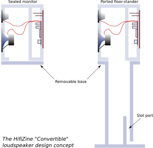
The size of the monitor is 198 x 326 x 300 mm (width x height x depth), including the base plate. The ported stand is a little over 600 mm tall, giving a total height for the floor-standing version of around 950 mm.
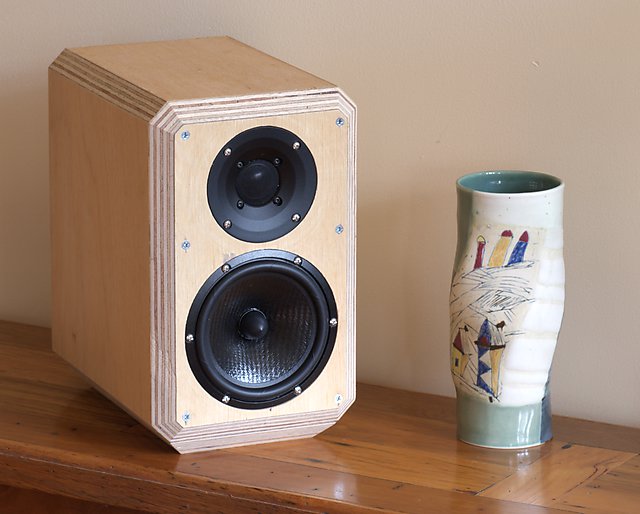
A prototype loudspeaker
The photographs below show the first prototype loudspeaker. The front edges of the enclosure are cut at 45 degrees to help reduce diffraction effects from the edges of the baffle. The baffles are not glued on, but held with screws so I can experiment with different baffle edge treatments and positioning of the tweeter. Since the prototype is for making measurements and ironing out kinks in the construction plans, I made it from a quarter-sheet of “marine ply” from the local big-box hardware store, but intend later to construct another pair from good quality Baltic Birch ply.
Preliminary equalization and crossover
I performed preliminary measurements of the speaker outside, with the speaker elevated. There was some environmental noise, and a strong reflection off the ground at slightly over 5 ms causing noticeable notches in the measurements, particularly at 300, 500, and 700 Hz. The off-axis responses are all cut off at 200 Hz because of the noise, and I’ve applied 1/6-octave smoothing to the graphs. But for now, this is adequate to assess the design goal of smooth off-axis response.
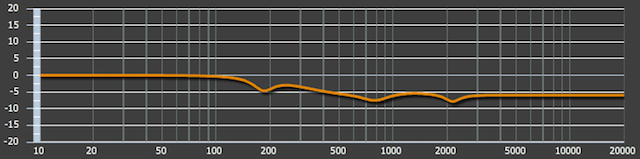
Figure 3 shows the measured response of the woofer in the above enclosure. At the top in blue is the response with no equalization, below it in red is the response after applying EQ, and then the horizontal off-axis responses at 15, 30, 45, 60, 75 and 90 degrees. As can be seen, the off-axis response of the woofer decreases smoothly up to around 2800 Hz, from where it drops more sharply, suggesting this as the upper frequency limit for a crossover (bearing in mind the considerations about off-axis response above).
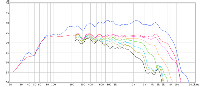
Figure 3. Woofer response before equalization and after at 0, 15, 30, 45, 60, 75, 90 degrees
The woofer EQ was fairly straightforward, with the largest component being a 6 dB shelving filter for baffle-step compensation. (This will most likely be reduced to 3-4 dB for in-room use.) The tweeter equalization is a little trickier. While the tweeter itself should give a reasonably well-controlled off-axis response, the baffle conspires against this, as sound at tweeter frequencies diffracts at the edges of the baffle and causes ripples in the response. This occurs even with this tweeter and the chamfered edges, and is easily visible in the measurements. It can also be predicted or confirmed with the use of simulators such as The Edge and the Baffle Diffraction Simulator.
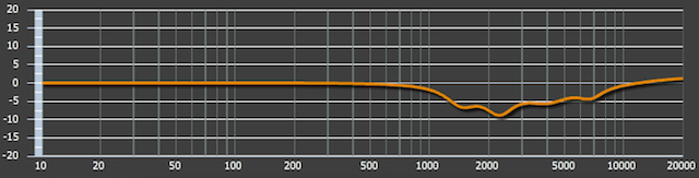
Figure 4 shows the tweeter response at 0, 15, 30, 45, 60, 75 and 90 degrees, without any equalization. While the off-axis curves (30 degrees and above) change fairly smoothly, the on-axis curve has some noticeable ripples – in particular, a peak above 2 kHz and a dip at 3 kHz. This raises the question of exactly which curve to optimize the equalization for: if we make the on-axis response flat, then the off-axis response will tend to have a bump at 3 kHz; if we make the off-axis response flat (to optimize the power response), then the on-axis response will have a dip at 3 kHz.
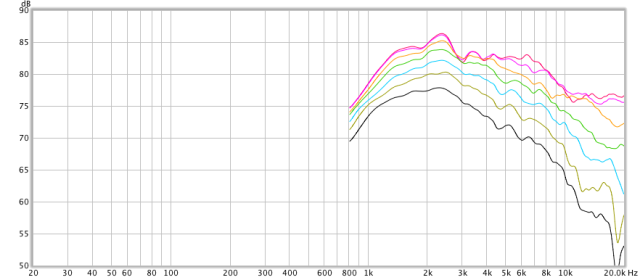
Figure 4. Tweeter response before equalization at 0, 15, 30, 45, 60, 75, 90 degrees
I decided to split the difference and equalize for the average of the on-axis and 30-degree measurements up to about 10 kHz, and see what happened. Figure 5 shows the result of this equalization, on-axis and horizontally at 15, 30, 45, 60, 75 and 90 degrees. The off-axis curves vary quite smoothly, and while the on-axis curve has some lumps in it, it’s still within a 4 dB window.
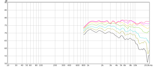
Figure 5. Tweeter response after equalization at 0, 15, 30, 45, 60, 75, 90 degrees
Can the baffle be improved or altered so that we don’t have to make this compromise? There are a number of methods used to address baffle diffraction, the best being the use of a curved baffle or a large rounded edge. We don’t really have room for that here and it’s difficult to do in a home workshop. Another is to offset the tweeter slightly from the center of the baffle, so that the diffraction effects are spread in frequency; albeit at the cost or inconvenience (for measurement and equalization) of asymmetric polar responses to the left and right sides of the speaker. And another is to put wool felt on the baffle to absorb the sound wave traveling along the baffle surface.
I’ll explore some of these at a future time. For now, let’s implement the prototype crossover! Figure 6 shows the distortion measurements of the tweeter with equalization in place. The SPL here is not high, but based purely on the distortion level, the plots suggest that the tweeter will operate well down to about 1500 Hz, so we can consider this as the lower limit for the crossover frequency.
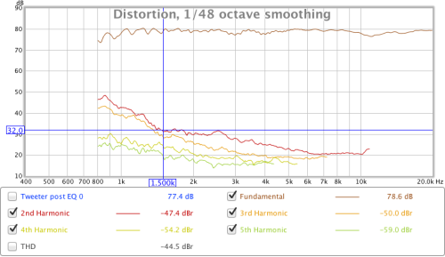
Figure 6. Distortion measurement of tweeter with equalization
Comparing Figures 3 and 5, the off-axis plots suggest that anywhere between the 1500 and 2800 Hz limits mentioned above will give an acceptable match, with around 1700 Hz looking like the optimum. At this point, I’m reluctant to “push” the tweeter too hard, so I decided on 2 kHz for this initial version. With the microphone positioned 1 m from the drivers and vertically centered between them, I measured a difference of 0.07 ms in the impulse arrival time, so this was added as a delay to the tweeter channel. The tweeter channel also needed several dB of attenuation to match the woofer level.
Setting a fourth-order Linkwitz-Riley crossover at 2 kHz resulted in the measured response shown in Figure 7 below. These curves have 1/3-octave smoothing applied to better show the trend in the off-axis response. Overall – and with regard to the goal of smoothly-varying power response – this is looking quite good already, so it will be interesting to see if the baffle tweaks discussed above can improve on it.
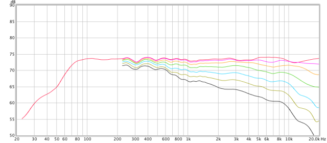
Figure 7. Combined response with LR4 crossover at 2 kHz, at 0, 15, 30, 45, 60, 75 and 90 degrees
Programming the DSP
Programming the equalization curves into the miniDSP plate amp is simplicity itself. The interface program or “plugin” (currently Windows-only) will immediately be familiar to anyone who has used miniDSP products before:
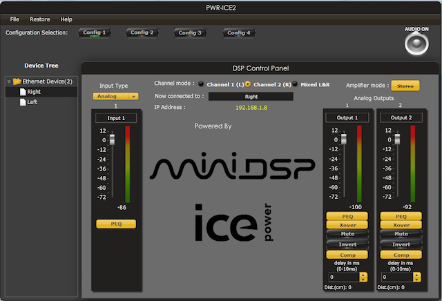
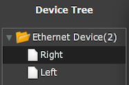
A potential hiccup is that the connection to the amp is via Ethernet and not USB, so outdoor measurements and equalization may necessitate locating a long Ethernet cable. The advantage in a typical stereo setup, though, is that you don’t have to swap cables as you do with USB in order to switch between amps – just click on the amp you want to configure in the control panel:
Programming the parametric equalizers for each output channel can be done either by setting each filter manually, or by importing a file generated by the REW auto-EQ function. I used the REW auto-EQ with a bit of manual tweaking to generate correction curves for both drivers. The woofer EQ is straightforward and consists mostly of the baffle-step compensation, plus a few mild notch filters. (Note: the notch just below 200 Hz is a bit suspicious, and is probably compensating for the ground reflection mentioned above. I expect the final EQ will not have this notch.)
The EQ for the tweeter implements the correction discussed above:
Concluding remarks
You may be wondering at this point how DSP and controlling directivity are related. The answer is that they aren’t, I just wanted controlled directivity to be a design goal of this speaker. The directivity of a speaker is determined by physical properties – driver cone/dome shape and size, driver faceplate or waveguide, baffle size and shape, and so on. The advantage of DSP is the ability it has to flexibly assert overall control over the frequency response. It enables different crossovers to be easily auditioned, and it enables the speaker’s response to be readily optimized for (for example) on-axis response or a few degrees off-axis.
Additional notes
- The power response would require hundreds of measurements to measure directly, and so is typically computed mathematically. Toole also provides related responses that can be measured more easily. For example, the listening window response is the average of the nine frequency response measurements at angles of +/- 30 degrees horizontally and +/- 10 degrees vertically. Another, the early reflections curve, is an average of 26 measurements at angles that mimic the directions of radiation that will result in first reflections in a typical listening room. Toole shows that the early reflections curve is in fact a good predictor of a loudspeaker’s measured in-room response.
- The terms “dispersion” and “directivity” are often used almost interchangeably, as in “controlled dispersion” and “controlled directivity”. They tend to have opposite meanings, with “wide dispersion” and “low directivity” meaning roughly the same thing. I’ve not found a formal definition of “dispersion” as it relates to loudspeakers, but it tends to be used to describe the pattern of or variation in acoustic radiation, sometimes in a general sense (as in “the plot shows the dispersion pattern of the speaker”) and sometimes more specifically as the angle between the -6 dB points of a beam. In contrast, the directivity index of a speaker is defined precisely as the difference (in dB) between the on-axis response and the power response, or (Toole p379) as the difference between the listening window response and the power response.
- The term “lobing” refers to the formation of “lobes” in the acoustic response, whereby some angles have full power radiated and some have none. It is an unavoidable consequence of the use of multiple sound sources. See Figures 1 and 2 in this Rane app note for examples of vertical lobing. Lobing also occurs in open baffle speakers because of the interference effects of the acoustic radiation from the front and rear of the baffle.
Acknowledgements
HifiZine gratefully acknowledges the support of the following companies and individuals:
- miniDSP, for providing the amplifiers used in this loudspeaker project.
- Seas of Norway, for providing the loudspeaker drivers used in this project.
- Duke LeJeune (AudioKinesis), Ammar Jadusingh (Soundfield Audio), and Patrick Dillon, for reviewing and commenting on this article prior to publication.


Nice..I have one of these ICE modules to play with already…maybe a 2nd one is on my radar now.
Those off-axis measurements look excellent.
Well done John, a nice result.
I like the cabinet design also with amp in its own vented section.
Is that venting adequate ? do the amp modules get hot ?
Thanks for the comment, Nigel. The modules don’t get very hot, you can feel warm air from the top vent after they’ve been on for a while, so the venting seems to work well but I don’t think it’s really necessary, this speaker isn’t making the amps work very hard. According to the spec sheet at 1/8 power into 8 ohms the amp module dissipates 11W, at full power 25W.
Any possibility this could end up as a DIY kit, with finished cabinet?
Hi Bruce, well I honestly don’t know! I’m not in the kit business but someone who is might be interested… any suggestions?
Am not really sure. I’ve never built a DIY speaker, so am just observing I don’t have the skills or tools to do a cabinet, and noting I’ve seen kits (say from Parts Express) that include all this. I suppose one potential rub for a complete kit is whether the plate amps/dsp could be included.
Heavens! Nice work, Johnboy. Here I thought you were all about open baffle speakers. My long time reference speakers are active if you didn’t know, tho not quite to your level of sophistication.
Hi Jim, thanks for the comment. I’m interested in a lot of things 🙂 I had actually forgotten that you run active speakers. I’m sure they are well designed.
So how do they sound? Noticeably better than commercial passive speakers?
Hi, I’m still running them with the preliminary EQ/crossover but so far everyone who’s heard them has commented favorably. I’ve been running my existing subs, after I get the ported bases done and a matching sub I’ll see if I can get more folks to have a listen.
Hello John. I look forward to hearing your impressions of the finished speakers, and thanks for a very interesting project. You mention adding ported bases. There’s something that worries me about ported active speakers, and maybe you can clear it up for me: as far as I can understand it, near resonance the port is reinforcing the bass by effectively adding a suitably-delayed version of the backwave from the cone..? I have also seen articles that imply that DSP can be used to fix the time domain ‘smear’ that would seemingly be caused by this. Intuitively I can’t get my head around how this would work. What would you have to do to the signal in order to kill the delayed version, and if you did, would you in effect be killing the bass reinforcement anyway? I suspect that what people are really doing is fixing a phase shift (as applicable to a steady state waveform), but *not* correcting the time domain smear (as applicable to a transient)..? Any views on this? Thanks!
Hi again, the port is a Helmholtz resonator, which produces output centered at a frequency determined by its dimensions and the air volume in the box. The result is more bass but a steeper rolloff (24 dB/octave). This rolloff has an attendant phase shift, and therefore a frequency-varying “group delay” related to how quickly the phase changes. With DSP, it is possible to linearize the phase shift, and thus zero the group delay. However, the processor/software in the PWR-ICE125 is not capable of this type of DSP. I prefer to avoid terms like “time domain smear” as they are not well defined, but linearizing the phase does “improve” the impulse response…
In the end, porting a small woofer is a compromise, though. Adding subs is a better albeit more expensive way to improve the bass response.
Many thanks for the reply, John. I suppose it’s possible to view the port in several different ways. Quoting from the Wikipedia description:
“… the backwave of the bass driver sound emission is inverted in polarity for the frequency range between the two resonances. Since the backwave is already in opposite polarity with the front wave, this inversion brings the two emissions in phase (although the vent emission is lagging by one wave period)”
The part that interests me is that the port is effectively emitting the cone backwave delayed by one wave period. So even if I shift the signal phase in DSP at those frequencies, I’m still going to get a delayed version coming out of the port, mixed with the direct, am I not? It is this that I was thinking of, wondering whether DSP can *completely* compensate for the effect of the port. But everyone uses ports, including Meridian, so I guess it’s not an issue.
Re. ports, maybe it’s useless to try and think of it intuitively! Can the system be deconvolved is the question, I suppose. In a real room, rather than an anechoic chamber, does it make the slightest difference anyway?
Hi again, I think you’re on the right track. I haven’t tried a ported system yet but you can linearize a sealed box easily enough. So, more on that later 😉
Hi John,
How are the follow up articles (i.e. Parts 2 & 3) of the project coming along? Looking forward to seeing them.
Keep up the good work.
Bruce M
Hi Bruce, thanks for the kind comment and your enquiry. The construction article is held up waiting for me to build another pair so I can take some decent photographs that reflect my current dimensions/drawings…. The ported base has been revised to include it’s own woofer to make a 2.5 way, similar to the concept I posted for the Convertible here: https://johnr.hifizine.com/2014/04/the-convertible-active-loudspeaker-revisited/
I’m sorry, woodwork is a very slow process for me…
Hey John,
Thanks for the excellent review!
I’m building a horn loaded sound system for sound reinforcement purposes, and these amps look like an excellent way to go. My only real hesitation are with the noise spec’s: [2 x 120W @ 1% THD+N, 20Hz – 20kHz, 4Ω, SE (both channels driven)], seeing as how a main goal is to have as good sound quality as possible (ribbon tweeters, biamped, dsp).
After listening to your system, what are your thoughts on this?? And has the system been stable??
Much thanks in advance,
Conrad.
Hi, to be honest for sound reinforcement I would use separate fan cooled amps, these are not thermally designed for continuous high power operation. I forget the thermal ratings exactly but they are in the B&O datasheet. You would have to ask miniDSP for the noise spec.
My pair are not currently operational as I’ve disassembled them to finish the boxes nicely. And, well… it’s taking time 🙁
Hey John,
Your project looks great!!
I have just a question, I’d like to think that u’ve made stereo speakers.
But each amplifier has an own volume control, the question is how u Balance the volume?
Regards,
Adrian
Hi Adrian, the volume control is, I think, really intended for when you are using one amp for a subwoofer. For stereo use, set the volume control on the amps to full on and control the volume “downstream” i.e. in a preamp (for analog in) or in computer/digital source.
Okay, thanks.
But I have another question, the Chassis u’re using have an different impedance.
Is this relevant or a problem when u connect them both to the same Amplifier?
Regards,
Adrian
Hi, no, not a problem. The drivers are connected to different channels. The maximum output power for the 8 ohm driver will be less (about half) but as long as that is not a problem, it’s fine. With this driver, 65W is plenty.
“You may be wondering at this point how DSP and controlling directivity are related. The answer is that they aren’t..”
Different crossover types and their order severely impact lobing, so If we consider lobing being part of directivity/dispersion problem domain then relation actually exists.
My recent observation was that with very steep crossover slopes effect of horizontal physical shift of HF driver (aka time alignment) to be almost inaudible compared to that of LR phase linear 4-th order filter probably because with steep filters lobing doesn’t change much. The steepness must be at least 8-th order, I used Hypex A2.100d amp for this and sequenced 4 second order IIR biquad filters. Even better results can be achieved with so called brickwall FIR filters, as suggested and explained here: http://www.prosoundweb.com/article/a_useful_tool_creating_applying_fir_filters/P1/
In this article Rephase tool was used together with miniDSP and OpenDRC 2×2.
PWR-ICE125 uses ADAU1445 SigmaDSP. Can it also be used with this software?
If not, Sigma has their own DSP programming software. Has minidsp OEM-locked the DSP chip? If not, reprogramming with Sigma tools could void warranty but also open up more features, like creation of brickwall FIR filters (see mentioned article) resulting in significant reduction of vertical lobing.
Unfortunately I haven’t yet found plate amps with built-in DSP and convenient software that provides FIR crossover filters and Room EQ in the same package. Any suggestions?
Ah, yes, that is true, that with DSP you can achieve a steeper crossover than you can with analog filters, which – as I understand it – will reduce the frequency range over which vertical lobing occurs. I’m not sure I understand the significance of the horizontal shift though…
I don’t know of any plate amps that can have FIRs programmed into them. It would be cool if there were…