Subwoofer Origami
In Prototyping a Dipole Bass System, I built a prototype open-baffle subwoofer using four drivers. I had found that a flat baffle induced vibration into the floor too easily, and so used a “push-pull” configuration to minimize mechanical vibration. This prototype subwoofer was constructed cheaply and quickly, and with an eye to building a more solidly constructed pair of them, I wondered what physical configuration I should use. In the process of exploring this, I realized that there are so many variants of the open-baffle subwoofer that it would be worth trying to write them down in some sort of sequence to explain them. This I have called “subwoofer origami,” because of the many ways in which the baffle can be “folded.”
A little theory
Consider a monopole source – that is, an omnidirectional point source. Monopole is a concept from electromagnetic field theory. As far as loudspeakers go, it is best thought of as a theoretical abstraction: the unrealizable omnidirectional point source of sound, and any given loudspeaker may be similar to this theoretical abstraction to a greater or lesser degree. A monopole radiates its field equally in all directions; this is shown at the left of Figure 1, with straight lines radiating from the monopole (the red dot). For a point source of sound, these arrows correspond to our intuitive notion of “rays” of sound; more precisely, they represent direction of air velocity as the positive pressure wave propagates outwards from the source.
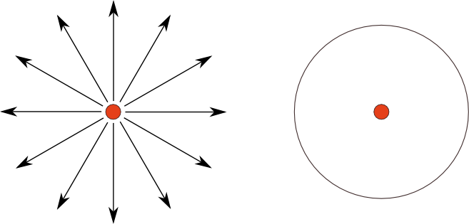
Figure 1. A monopole’s field lines (left) and equipotential (right)
We also think of the sound from a point source as emanating in a sphere. For a point source of sound, we expect that the sound pressure level will be the same at a constant distance from the source. This is known as an equipotential, and the equipotentials are always perpendicular (at right angles) to the field lines. In the case of a monopole, this leads to a spherical radiation pattern, as shown at the right of Figure 1.
A dipole consists of two monopoles with opposite polarity, separated by a distance that we will call D (after Linkwitz). At the left of Figure 2 are shown a positive monopole in red and a negative one in blue. The field lines travel from the positive to the negative monopole. When we take an equipotential perpendicular to the field lines, we obtain a curve as shown on the right. This is the “figure of 8” radiation pattern of a dipole.
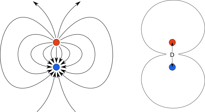
Figure 2. A dipole’s field lines (left) and equipotential (right)
As mentioned above, monopole and dipole are theoretical concepts, and any real loudspeaker can only approximate the behaviour of either of these. This approximation applies over a limited frequency range – for example, conventional boxed loudspeakers will behave like a monopole at low frequencies (less than a couple of hundred Hertz, say), because the wavelengths are large enough that they “wrap around” the box, effectively making the speaker into an omnidirectional source at low frequencies.
One way to approximate a dipole loudspeaker would be to position two monopoles a distance apart, and drive them out of phase. Another way is to use a single driver with no box. Since the radiation from the back of the cone is out of phase with the radiation from the front, all we have to do to separate the two sound sources is to put a baffle in the way. As shown in Figure 3, the effective separation D is about half the width of the baffle.
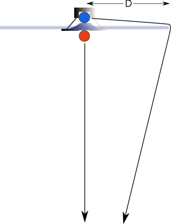
Figure 3. Simulating a dipole with a cone driver on a baffle
Again, this is an approximation to a true dipole. For a detailed look at how practical considerations affect the radiation pattern of an open-baffle speaker, see the paper Open Baffle Dipoles: How they work, and how to use them well by Rudolf Finke.
An unanswered question at this point is “why?”. Primarily, because a speaker that has the figure-of-8 radiation pattern shown to the right of Figure 2 does not radiate sound energy either to the sides or towards the ceiling. At low frequencies, this means that you have an additional tool that can help tame room modes. My experiments to date don’t suggest that it’s automatically true that a dipole speaker will solve or reduce room problems, but with measurements and positioning it can. Dipoles also have, for the same on-axis sound intensity, less total sound energy projected into the room, as shown by Linkwitz. And, there are other reasons such as that they are easy to build and interesting to experiment with.
The drawback of dipole speakers is that output drops with decreasing frequency, so equalization and other methods are needed to compensate. That is why we care about D: the higher it is, the less dipole loss (everything else being equal) there is at low frequencies. However, this is only one factor in successful deployment of a dipole subwoofer, as dramatic differences can also be observed with placement, for example. In addition, the figure-of-8 pattern only holds at frequencies where the wavelength is large relative to D; but since this article is about subwoofers, what happens at higher frequencies is not a concern here.
Origami
Let’s now explore the different types of baffle we can use. These will be an approximation to a dipole in various ways. We start with a driver in flat baffle, sometimes also called an “I-frame”:

Flat open-baffle speaker, showing direction to the listener
This is a cross-section, looking down on the speaker from above. The listener (in this and all following diagrams) is assumed to be “below” the diagram. We will also assume that the panel is high enough not to cause an acoustic “short circuit” around the top of the baffle – that is, the baffle must extend at least D above the driver.
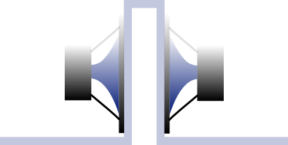
This is obviously a simple speaker to build, and at low frequencies is a reasonable approximation of a dipole, but it has two major drawbacks: it’s large and unwieldy, and the panel vibrates in response to movement of the heavy subwoofer cone. We can address the second item by using two drivers in a “push-pull” configuration. In order for it maintain a dipole radiation pattern, we need to “fold” the baffle like this:

Folded baffle
The two drivers are wired out of phase, which should (in theory) reduce even-order distortion, and again, we assume that the baffle is tall enough that we don’t create an acoustic short-circuit around the top. D is about the length of a “wing.” This is the configuration that I used in my prototype, and it’s relatively quick and easy to make, but it’s still large (from the front) and visually imposing.
Let’s make it more compact now, by folding the baffle back around the drivers, like this:

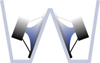
Linkwitz W-frame
The speaker can be made shorter, to just the height needed to hold the drivers, by placing a panel on top. D is approximately the depth of the construction (from front to back, or from top to bottom on the diagram). This is commonly called a “W-frame” and is attributed to Linkwitz.
One of the issues that arises when folding a baffle like this is the creation of resonances. An air column that is open at one end and closed at the other can resonate at the frequency at which the column length is a quarter-wavelength – see for example Closed and Open Pipes. Linkwitz measured this peak at 270 Hz for the W-frame dipole woofer used in the Phoenix loudspeaker.
Let’s go back to the flat baffle, and then fold it a bit differently, like this:
Slot-loaded open baffle
This time, the woofers are wired in phase, but the “slot” between them is quite narrow, with a suggested area of around one-third of the combined area of the two driver cones. This is the Nelson Pass slot-loaded open baffle. The “compression” in the slot is reported to lower the Fs and raise the Qts of the drivers. Pass added a second baffle containing a fullrange driver on top of this, thus greatly increasing the effective baffle height.
If we now fold the baffle back around the drivers, as we did for the W-frame, we arrive at a new variant, which I have dubbed the “slot-loaded W-frame”:

Slot-loaded W-frame
The “slot-loaded W-frame” still has a slot-loading effect on the woofers, but is more compact. We can build it just the height needed to hold the drivers, and put a top panel on it.
As noted earlier, all of the arrangements with a “slot” will have a quarter-wave resonance according to the slot depth. Let’s go back to the slot-loaded W-frame and “open up” the slot to try and reduce this resonance, like this:
V-frame
I’ve dubbed this the “V-frame.” I did try a quick mockup a while back and didn’t see a prominent resonance peak in the measurement, but I do need to make and measure a proper prototype to be sure about this. The intention here is to keep the slot opening fairly small to minimize the net force exerted on the cabinet. If, however, we relax that requirement and open the two drivers up further, we arrive at what is commonly referred to as the M-frame:

M-frame (push-pull)
There’s now room to turn one of the drivers around again, into “push-pull” mode, so they need to be wired out of phase. This construction is generally used turned at 90 degrees i.e. stood on end.
This configuration can also be “cut in half” to use a single driver, a tactic that can be used to make a frame that is narrower than the driver diameter. This is called an N-frame and of course, with a single driver, there is no force cancellation:
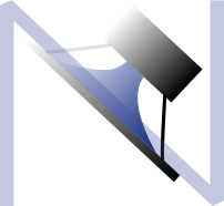
N-frame
Even with the M-frame, we have lost much of the force cancellation achieved by using push-pull woofers. By vector arithmetic, the M-frame has 0.707 of the force generated by the drivers trying to move the frame backwards and forwards. So let’s continue the trend and open the baffle up completely, to arrive at an H-frame:
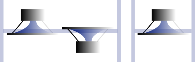
H-frame
The H-frame is popular in DIY circles, although it offers no force cancellation. The double-woofer version tends to be used with smaller drivers (12″ and below) and the single-woofer version with larger drivers (15″ and 18″). The single-woofer version in particular is quite compact and has good bass output for its size.
The design is quite simple, and easily allows some trade-offs to be made, such as increasing the slot depth to obtain more output – the effective separation D is about equal to the total depth of the frame. Both of them will have a resonance peak but it’s more likely to be noticeable with the single-woofer version. Rudolf Finke suggests that the quarter-wave resonance begins to be troublesome when the slot depth exceeds half the width of the frame.
Let’s return briefly to the slot-loaded W-frame, and move the outer sides of the baffle inwards. If we cut a hole for the magnets and keep going, we arrive at a “ripole”:

Ripole
The ripole applies loading at the rear of the drivers as well as the front. This configuration was invented and patented by Axel Ridtahler, with the goal being the most compact dipole subwoofer with lowest Fs possible. The radiation pattern is now moving away from dipole, as illustrated in this comparison.
The above configuration is called BMC (for “blow motion control”). An alternate configuration uses just a single driver. The slot area at the front is 1/4 to 1/3 of the cone area, and the back chamber is made as small as the driver allows.
Finally, before closing, it’s worth mentioning another popular “folding” of the baffle. If we go back to the flat baffle with single driver and simply fold the baffle back around the driver (and put a lid on it), we arrive at the U-frame:
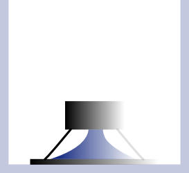
U-frame
The U-frame was popularized by John Kreskovsky. At low frequencies, the U-frame acts as a dipole, but this deteriorates as frequency rises. Kreskovsky shows, in the article The U-Frame Woofer System, how damping material in the chamber makes this construction have a cardioid polar response across a broad range. But we have moved well away from dipoles now, so that is perhaps a subject for another day.
Concluding remarks
So, what to build? With so many choices, it’s hard to given any definitive answer. It will depend on your design criteria as well as the specifics of the drivers that you have or that you can purchase at a reasonable cost. For example, if a narrow baffle is important to you, an M-frame or H-frame with two woofers may be the best option. If you plan to cross over to your midbass at a relatively high frequency (i.e. above 200 Hz) then a configuration with a low resonance peak is likely to give the best result, even if at the cost of low-frequency output. Or, smaller drivers can be used to increase the frequency of the quarter-wave resonance, but at the cost of either reduced output or using more drivers. There’s no simple answer.
Build and measure!
Acknowledgements
This article was improved greatly by comments from Rudolf Finke, Steve Dodds, and Ammar Jadusingh.


Thanks for this article John. This is really helpful to us DIY types. Photos of industry examples next to the diagrams would a useful addition.
thank you for your very contentfull and easy to understand explications. It was the missing link i needed to build my best subwoofers. Ripol rules .
Lucian
Published measurements for Ripoles show significantly different data at low SPL vs. high SPL. An equation for minimum W-W separation based upon woofer construction is necessary. .
Hi Johnson, would you be able to provide a link to those measurements? Thank you!
Hi John,
Can you advise which design will be the best option for dual 21″ subwoofer with xo point less than 80Hz 24dB?
Thanks
Hi Anshari, you would have to build a prototype and measure it, but I would use a W-frame, and try some “slot-loading” depending on the driver’s Fs and Q.
Hi. Thanks for this article.
I was wondering if you knew the effects on the N-frame subwoofer if one were to lengthen one of the sides of the subwoofer to the rear. In your diagram, I would be referring to the upper left side. I was thinking that while the front and rear won’t be totally symmetrical, the added ‘wing’ might take advantage of some of the ‘dead’ space behind the speaker and cut down a bit more on the open baffle cancellation without providing quite the resonance of a U frame in the rear. Also, what is the radiation pattern of the N frame? Is it from the ‘mouth’ of the ‘N’ or is it along the plane of the driver? I hope these questions make sense. Thanks
x
x
x
x x x
x x x
x x x
x x
Hi, the nulls are roughly to the sides in all cases with the listener “underneath” the diagram. I think your suggestion will have a small effect on the bass response but only small.
An H-frame wich is much wider than the diameter of the woofer (say twice) must have a dipole distance D much higher than its total depth . Logic dictates this as other wise an I-frame would have a D equal to the thickness of the baffle
Not really, you have neglected the path over the top.
Hallo John your article is absolutely amazing!
unfortunately I am not able to understand whati is the best configuration for me, can you give me some suggestions?
I have 4 woofer w15 Lii Audio designed for open baffle (you can see the specs here)
and I also have a pair of S10 (Lii Audio) in Liionidas open Baffle.
I want to change to try the S10 in an OB panel like Big Betsy design ( ) the measures are raffly 106X80
and I want to use two woofers for each channel, what do you think could be the best configuration to mach with the S10 Dipole?
Thank you
Aldo
hello,
could you please give me a few names of bookshelves less than 500 us including older models that are good with heavy metal music. so less distortion and capable of sorting out compressed music and fast drums.
thank you vert much!
Pls consider this setup : a woofer of size say 10 inch mounted in the center of a round baffle that has a radius of 40 inch (that’s extreme I know) . Now imagine putting that round baffle in an H-frame of lenght 20 inch , essentially a cylindrical tube of length 20 inch and radius 40 inch . If you say that the dipole distance is only 20 inch , the length of the H-frame , then you get the following contradiction : by removing the H-frame , you get an I-frame with dipole distance 40 inch . How on earth can the dipole distance grow , when I remove the H-frame ?