Digital Direct – the miniDSP Stack
Some time ago, the miniDSP folks came up with something they call the “miniAMP” – a small Class D amplifier card. This was designed to be “stacked” together with the miniDSP (digital signal processing) and miniDIGI (digital I/O) cards. With a total of 40 W of power, and considering the plethora of Class D boards and modules available lately, I have to admit that this didn’t seem all that interesting at the time.
My interest was piqued, however, when I was asked by a friend to help her with replacing an aging stereo unit. In a discussion about speaker placement, it became apparent that your typical “audiophile” placement was simply not going to be accepted. The speakers had to be small, unobtrusive, and close to the walls – preferably mounted on them. One was going to be put in a corner and another along a wall. I realized that – together with a miniDSP to act as crossover and equalization – a miniAMP would be a perfect fit for a situation such as this.
Later on, I became more intrigued when I realized that I had been thinking about this set of boards the wrong way! I had thought that one would purchase a particular combination of boards for a specific project, assemble them into a chassis, and be done with it. That is, after all, how they are marketed. But, as an inveterate tinkerer and experimenter, what I can build with something is to me less interesting than how many different things I can build with it! The light came on, and suddenly I knew why I “had to have” a miniStack (as I have dubbed it).
The miniDSP stack
What it is
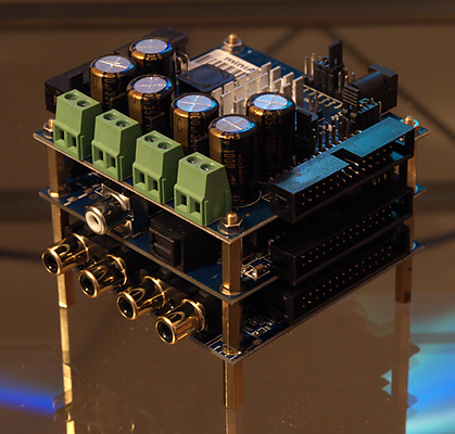
There are three boards in the miniStack, which provide digital I/O, DSP, and Class D amplification. The boards communicate using I²S (or IIS, for Inter-IC Sound), a simple interface standard originally designed to carry stereo digital audio signals between chips on a printed circuit board, such as you might find in a CD player or DAC.
In the miniDSP system, four sets of I²S signals – thus, four stereo signals – run between the boards, carried by ribbon cables. Jumpers on each board select specific signals as inputs to that board. In combination, the three boards implement the functionality shown in the figure below. Internally, all signals are routed using I²S, so each line on the “inside” of this diagram represents a stereo signal. On the “outside,” each line is a single physical connection to the board.
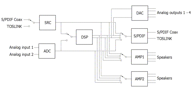
The miniStack – miniDSP, miniAMP, miniDIGI
The blocks in this diagram are:
SRC – sample rate convertor. The miniDIGI board has a chip on it that converts a digital signal at any sample rate that you would care to feed it, into a 48 kHz version of the same.
ADC – analog-to-digital convertor. Left and right signals on the analog inputs are sampled and converted into a 48 kHz digital signal.
DSP – digital signal processor. The processor accepts a stereo signal, and generates two stereo (I²S) signals. The specifics of what comes out depend on the software “plugin” loaded into the DSP, but typically the DSP implements a 2-way crossover and equalizer.
DAC – digital-to-analog convertor. The four channels (two I²S signals) output from the DSP are converted into analog line-level signals.
S/PDIF – any one of the I²S digital signals can be selected for output as S/PDIF (coax or optical). So, the digital input, the output from the ADC, or the outputs from the DSP, can be output as a digital signal.
AMP1 and AMP2 – Class D amplifier. Each of these blocks accepts one I²S signal and outputs one or two audio signals capable of driving speakers.
As an aside: I find the miniAMP intriguing because it accepts I²S as its input – it never “sees” an analog signal. In effect, it is like a high-power DAC. While the specifications of the chip don’t suggest extreme high-fidelity performance (well, you are getting four channels of amplification for only $60), I can’t help wondering if this is a precursor of the future of audio. I mean, why bother going through a digital-to-analog convertor only to then sample the analog signal so as to convert it into a switching waveform… Is the future of mainstream hifi “digital direct”? I guess we will see.
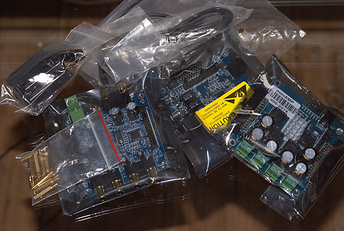
In the meantime, I have in my hands a small pile of boards that need to be assembled into a functioning stack.
Connecting and configuring the stack
To get up and running with the miniStack, I’m going to suggest that things be done in the following order:
- Set up the software plug-in
- Confirm that you are able to “talk to” the miniDSP board
- Set the configuration jumpers on the three boards
- Wire up the volume control potentiometer
- Assemble the stack
- Check operation of the stack
Depending on your familiarity with the miniDSP system and your experience with DIY electronics, you may want to skip over some of these sections. Regardless, though, you will need to refer to the manuals for each board: miniDIGI User Manual; miniDSP User Manual; miniAMP User Manual.
In this article I will set up the miniAMP in 2-channel “bridge-tied load” (BTL) mode, so each speaker output will be driven by two sets of output devices operating in opposite phase, in a similar manner to the bridged connection function common with pro-sound amps. This has an interesting consequence, which is that the DC blocking capacitors that are needed in “single-ended” mode are not required – they are bypassed in BTL mode and simply out of the circuit. The whole analog circuit is DC-coupled with no capacitors in the signal path. Whether it makes an audible difference, I cannot at this point say.
1. Set up the software plug-in
If you haven’t used a miniDSP before, you’ll need to purchase a “plug-in” along with your hardware. The plug-in is the software that runs on your computer, and controls the miniDSP board via a USB connection. Once the board is configured, the USB connection can be removed – there is no need to leave the computer connected to the miniDSP board.
For most people, I would suggest using the “2.1 PEQ” plugin, which will work as a two-way crossover as well as a 2.1 crossover. (The regular 2-way crossover does not work well with the miniAMP because of the way the output channels are routed to the I2S signals.) After installing and starting up this plugin, you will see a screen as shown in the screenshot below. The diagram at the top of the screen shows the processing flow in this plug-in, and each block can be clicked-on to show and adjust its settings. The default settings are mostly good for our initial purposes, but you will at some point need to turn off the crossover filters; see my earlier article for information on how to navigate and adjust the crossover settings.
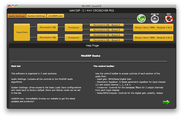
miniDSP 2.1 plugin startup screen
2. Connect to the board
Let’s just confirm that the miniDSP board is operating correctly. This will ensure that we have a checkpoint where we verified correct operation, in case something goes wrong later on. At this point, you can simply place the board on the envelope it came in. However, do not place the envelope on anything metal – that is asking for disaster. Put it on a wooden or glass surface.
Plug the supplied USB cable into the miniDSP board, and the other end into an available USB port on your computer. You will see a blue blinking LED come on. So far so good.
Then, in the 2.1 plugin, click on the Sync button:
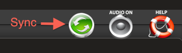
The Sync button
You should see a dialog as shown below. Click on “Upgrade and Synchronize.” (The next time you sync, you will get a “Synchronize” button.)
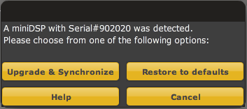
Synchronization dialog
After a few seconds, the sync will be complete:

Successful connection
From this point onwards, any changes made in the user interface will be downloaded directly to the miniDSP. At this point, however, we have made no other connections to the board, so unplug the USB cable and proceed with the following steps.
3. Set the jumpers
Because of the flexibility of the components in the miniDSP system, it is necessary to ensure that a number of jumpers are configured correctly. The user manuals for each board, linked above, should be checked to ensure that you have the various jumpers set correctly. If that feels like you are reading the manuals for the Space Shuttle (and I can’t say that I would blame you), then the application note Jumper Chart – 2way Configuration has most everything you need to get going.
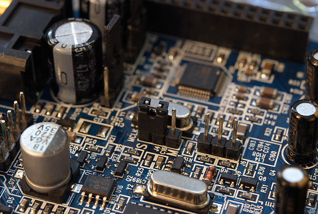
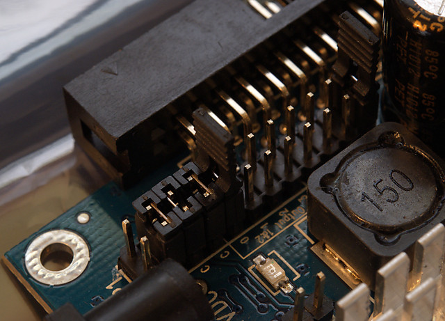
The key items to take care of are as follows, with each point corresponding to a photograph below (click on any photo for a larger version):
- The miniDSP must have the MCLK jumper moved to the “Slave” position
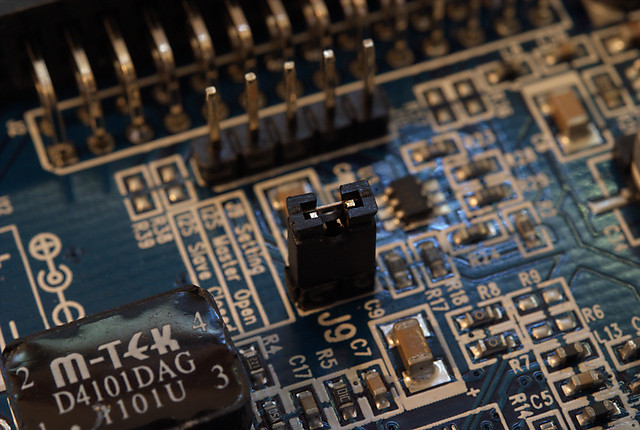
- The miniDIGI must be configured as I2S slave
- The source selection on the miniDIGI should be set to SPDIF #1, and the I²S in/out selection as shown in the photograph
- On the miniAMP, remove the Config1 jumper and leave the Config2 jumper there. This selects 2-channel mode.
- On the miniAMP, select I²S channels 0 and 1 as input for 2-channel mode (see note below)
- Ensure that the four bridge mode jumpers are in place.
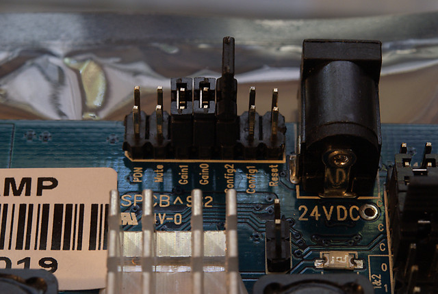
Note: with I²S channels 0 and 1 selected, outputs 1 and 2 of the PEQ 21 plugin will be routed to the miniAMP. In general, it’s probably better to select I²S channel 2 and 3, so that plugin outputs 3 and 4 supply the miniAMP. This then allows outputs 1 and 2 to be used for a mono sub feed.
4. Connect volume control potentiometer
Next, we need to wire up the volume control potentiometer. This requires that you obtain a small item called a “three-pin header,” which looks as shown in the photograph below. You don’t have to use one of these – you could just solder wires directly to the pins on the board. I prefer to make up the header as I can always remove it or make another with longer wires, etc. I used some strands of wire out of a CAT-6 network cable (excellent cheap hookup wire!), which I soldered to the small pins. These are then inserted into the header.
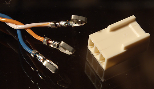
Assembling the 3-pin header for volume control
Now, the other ends of the wires are soldered to the potentiometer. The manual recommends a 10k linear pot. There is a bit of an issue here, which is that the miniDSP doesn’t implement a logarithmic volume curve, so some people have commented on the miniDSP forum that a logarithmic pot may give a volume response closer to what is expected. At any rate, I only had a 50k logarithmic pot in my spare-parts box, so I used that. (Later on I’ll replace it with a cheap 10k pot.)
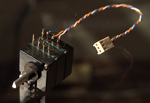
miniDSP volume control
With the wiring done, plug the header onto the header pins. Make sure that the end of the pot that is normally grounded is connected to the pin marked as a a square in the user manual. (If you get it wrong, you will have to partially disassemble the stack and reverse it.)
Note: the range of the volume control is limited, and does not reach infinite attenuation (zero volume). While suitable for experimenting and some limited situations, it is not really suitable for use as the primary volume control of most audio systems. Suitable volume control can be accomplished at the digital source, or prior to the analog inputs with an attenuator or preamp.
5. Assemble the stack
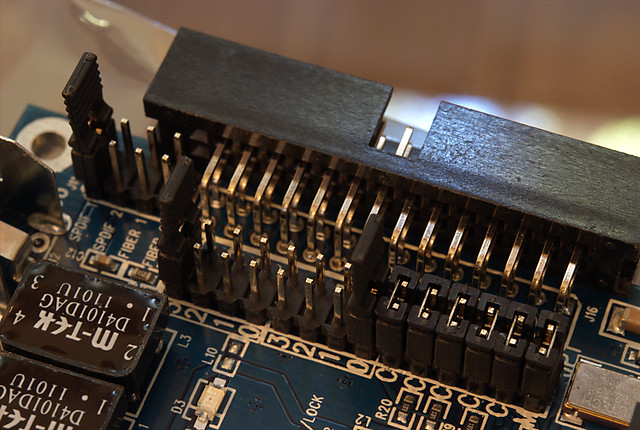
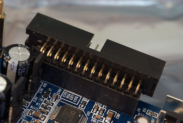
Now we can assemble the stack of boards. More detailed photographs are shown below. Before proceeding, though, I would just note that my miniDSP board came with a mounting lug on it that interferes with the PCB standoffs. This is used when boards are mounted into the “2×4” case, but it is not needed here. This lug is shown in the photograph below, and it will need to be removed before proceeding. (If this is difficult for you, all I can suggest is contacting miniDSP support.)
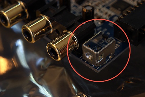
This lug needs to be removed
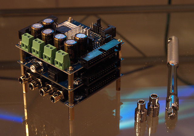
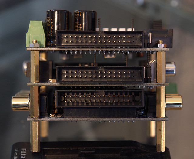
The following steps are shown in the series of photos below (click on any photo for a larger version).
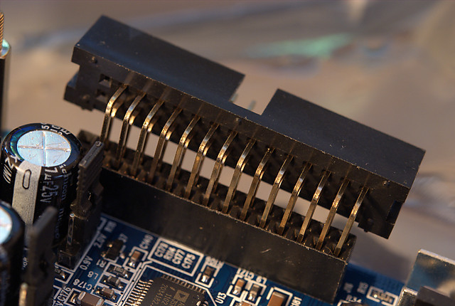
- Insert the supplied adapters into the miniDSP board. (Photos 1 and 2). Firm pressure will be needed, but don’t force it.
- Use the supplied PCB standoffs to mount the three boards on top of each other. Take care with the orientation. Apply a small amount of pressure so that the standoffs hold firmly, but take care not to over-tighten. Once done, you should have something that looks as in the fourth photograph.
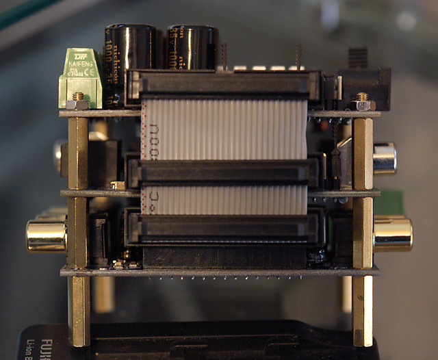
- Insert the supplied jumper cables. The fifth and sixth photographs show the “before” and “after.”
6. Confirm operation
You will now need to connect a power supply. Any suitable supply between 12V and 24V can be used. You only need to connect it to the miniAMP board, and the other boards will take power from there. With the power turned on, you should see blue LEDs on each board:
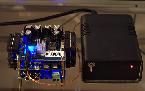
Applying power to the miniDSP stack
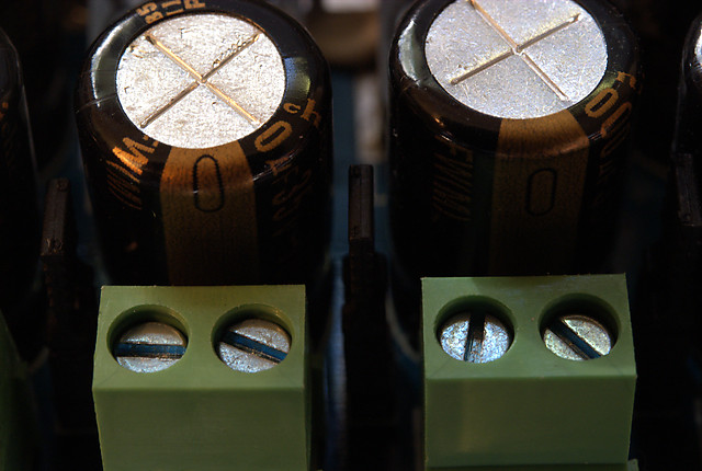
You can now reconnect the USB cable and confirm that you are able to connect to the miniDSP. Turn the power off again, and connect speaker cables to the miniAMP. The photograph below shows how speaker cables are connected when the miniAMP is configured in BTL mode:
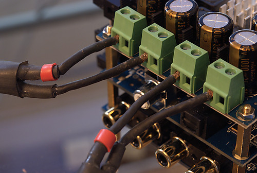
Connecting speaker cables to the miniAMP (in bridged mode)
Finally, connect a digital source to the miniDIGI board. Here is a photo of the stack from above, with all wiring shown:
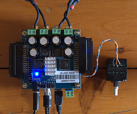
miniDSP stack with all connections
In the System Settings pane, enable the digital input and the volume control:
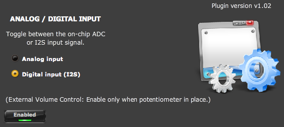
System settings screen
Turn the volume control all the way down, and press Play on your CD player. Be ready on the stop button, just in case you have the volume pot wired backwards. If all is well, you can sit back and listen to some music!
Concluding remarks
For $200 – plus postage and power supply – this is a pretty darn neat little experimental platform, I must say. I can see a stack of uses for it…
It will certainly be put to good use in for prototyping and measurement of a couple of active speaker projects that I have in mind – I mean, why bother hooking up multiple amps when you can get the whole lot in a 4″ cube? I’ll describe such a project in a future issue. Until then…


John,
I can’t thank you enough for tutorials such as this. It’s very well written, as is your minidsp 2.1 tutorial for subwoofer integration you wrote one year ago. The most important diagram for me was your 1st one in this tutorial…i.e. ministack. It’s a powerful all in one integrated platform. Such simplicity for the tinkerers amongst at our fingertips, how exciting! I don’t know how they compare to a typical ‘high end’ system but for experimentation, $200 is a mere pittance for this level of flexibility.
Hi Anand, thanks for your comment – much appreciated! Having to draw the diagram helped me enormously – I’m a strong believer in writing about what we do, it helps me as much as anyone, I think sometimes.
Excellent. I have been thinking about ordering one of these and I think I am now going to go for this 3-part kit. Thank you so much for the write-up!!
Hi Kyle, glad you found it informative. This evening I’m using it for measuring some prototype tweeter mounts. It’s helpful to have a flat on-axis response (by using EQ) so you can see how the response changes as you move off-axis. A few days ago I was using it as a two-way crossover for a new mid-tweeter driver configuration for my dipoles.
Hej.
So what about audio quality using the miniAMP? I own some old lowther horns, which are kind of bitchy when it comes to amps. I have been trying lots (on a students budget) and finally settled on an old Yamaha CR-800, which sounds great.
I am wondering if this kind of stack could help me with lot´s of my problems, like bass integration and the drivers “shout” at certain frequencies. Trying to dampen it with passive electronics, i killed the beautiful horn dynamics.
I´m using an iMac with an firewire audio interface and a turntable as audio sources. Would you recommend to get the whole stack: iMacs Toslink > miniDIGI > mini DSP > miniAMP, or only a miniDSP in the pre-out/main-in channel of my trusty old yamaha?
Hej lukas, I’m not sure how much EQ can help horn “shout” – it could be more complicated than just a frequency response issue. I haven’t had a chance so far to set up a straight (as much as it can be done) amp-amp comparison. With regard to the digital interface, I think it makes a lot of sense to use a miniDIGI from a computer source, my main system does that. However if you also need analog input, with the small board used in the “stack” it’s slightly inconvenient for everyday use to switch between the analogue and digital interfaces as you need the USB interface running and connected – although there is, I now recall, a way to do it with a physical switch as well… OK, that’s described in the miniDIGI manual.
Hi,
I have read your writings about the miniDSP. I’am planning to build also an open baffle speakers with 2 x Peerless SLS12″ per (stereo) channel. I have a problem to choose amplifiers to my project. After reading this article miniAMP seems perfect except small power output. So what is your opinion? Can miniAMP (2.1 configuration) drive two SLS elements? Have you tried to drive your 4 way open baffles?
Hi Kimmo, thanks for the comment. The miniAMP is not enough power for an open baffle woofer. In my experience it’s better to have more power for an OB woofer than not enough. I would be inclined to perhaps look into amplifier boards from connexelectronic.com for that task as they seem quite well thought of and not expensive. Although there are many others supplying DIY boards at various costs.