Subwoofer equalization and integration with the miniDSP 2×4
This is a tutorial on using the miniDSP 2×4 “DSP in a box” for equalizing a subwoofer and integrating it into a two-channel audio system. This article, hopefully the first in a series of articles on the miniDSP board and peripherals, introduces the basic concepts of crossovers and equalization using the miniDSP.
What it is
The miniDSP is a small digital signal processing (DSP) circuit board intended as a building block for applications such as active crossover, room and speaker equalization/correction, and so on. In this article I am just going to focus on the simplest possible choice – the miniDSP 2×4. (PDF product brief here.) This is a standalone unit containing just the miniDSP circuit board in a small case, for use “as is,” without use of any of the growing range of peripherals and add-ons being created for the miniDSP board. According to the folks at miniDSP, the miniDSP 2×4 unit was created as a “plug and play” option to allow a much wider user base to enjoy the benefits of DSP in their own systems.
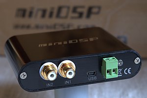
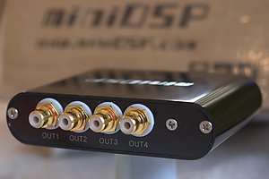
The miniDSP 2×4 shows up in your letter box as a small case, about 110 x 80 x 25 mm in size, with two RCA input connectors and four RCA output connectors. In addition, there is USB Mini-A connector, and an optional DC plug with screw terminals if you wish to use an independent power supply. (By default, the miniDSP 2×4 is powered from the USB connector.)
Inside this teensy little box is an embedded digital signal processor (DSP), along with power supply regulation, a two-channel analog-to-digital converter (ADC), and a four-channel digital-to-analog converter (DAC).
Having played with one of these for a couple of weeks now, my take on it is that this is just what the miniDSP people say: a great way for anyone to get started with DSP in their own system. It’s inexpensive, and easy to use, as I hope I will demonstrate in this article. Even if you don’t normally consider yourself a “do-it-yourselfer,” you may want to consider getting one of these fun little units to play with and learn something new about your audio hobby!
System configuration
Because of its inherent flexibility, the miniDSP only does something useful when you load a “plugin” into it. This is an additional software purchase from the miniDSP online store, for the very low price of USD10 each. For our purposes, we will need to buy the “2way PEQ 21” plugin. A day or two after buying it, you will receive an email telling you that you can download the plugin from the site. Just log in, download it, and follow the installation instructions.
The miniDSP software works on both Windows and Mac platforms. I’m taking the screenshots on my Mac laptop, so if there are minor differences from what you see while running the miniDSP software and what my article shows, platform differences are the most likely explanation.
The following diagram shows how I’m going to assume that the system will be connected for the purposes of this tutorial:
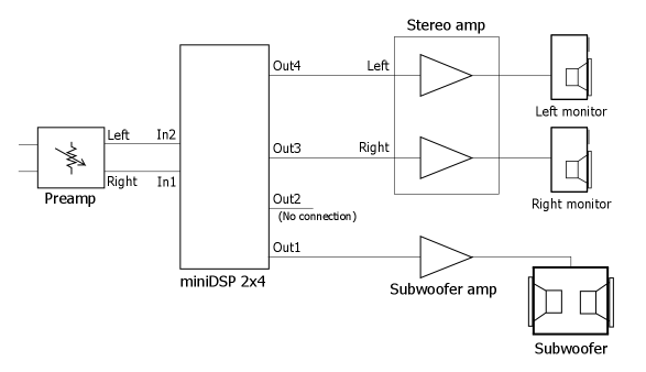
Figure 1. System diagram with miniDSP
So, what we have here is a pair of stereo speakers driven by a stereo amplifier, and a single subwoofer with its own dedicated amplifier. I’ll be using one of my own systems as the example system, which uses a pair of sealed mini-monitors as mains, and a dual 12″ sealed subwoofer driven by a bridged QSC amp as a single subwoofer channel. Note that the miniDSP needs to be driven by a low-impedance source, so most “passive” preamps are not a good match for this configuration.
In the rest of this tutorial, we will be working through a series of steps, as follows:
- Getting connected. This section explains how to connect the miniDSP to your system and get your computer “talking” to it.
- First audio steps. This section uses the miniDSP to set up a basic crossover between the mains and the sub.
- Doing in-room measurements. This section explains how to get started with doing in-room measurements.
- Measuring the subwoofer. This section explains how to measure the subwoofer’s in-room frequency response, with my measurements as an example.
- Applying equalization. This section explains how to use the miniDSP to correct the subwoofers’s in-room frequency response.
- Integrating the mains. This section explains how to fine-tune the crossover settings and match the sub to the mains using the miniDSP.
It’s quite a long tutorial, and you may wish to review each section before charging ahead! While the specifics of my measurements will no doubt be different to yours, the general principles will I hope come across in a useful enough way for you to apply them for yourself.
1. Getting connected
Having unwrapped the miniDSP 2×4, you will need to get it connected into your system. The diagram above shows the key connection points. Note that if you currently have your subwoofer connected using the speaker-level outputs from your main amplifier, then you will want to disconnect those. Instead, you will be taking output channel 1 of the miniDSP and connecting it to the line-level input of your subwoofer amp. If your subwoofer has an inbuilt lowpass crossover, you will need to bypass it, and also set any phase control to zero.
Note: make sure that everything is powered off while you make these connections!
Connecting the miniDSP board to your computer is straightforward. Just connect the provided USB cable from the miniDSP 2×4 to a spare USB connection on your computer. If you are using a desktop computer and not a laptop, you may find the provided cable to be on the short side. If so, you can purchase a USB extension cable on eBay for a few dollars. I would recommend a 2m or 3m cable, but no longer.
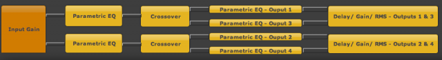
Start up the miniDSP plugin software. You will see a screen that looks like this:
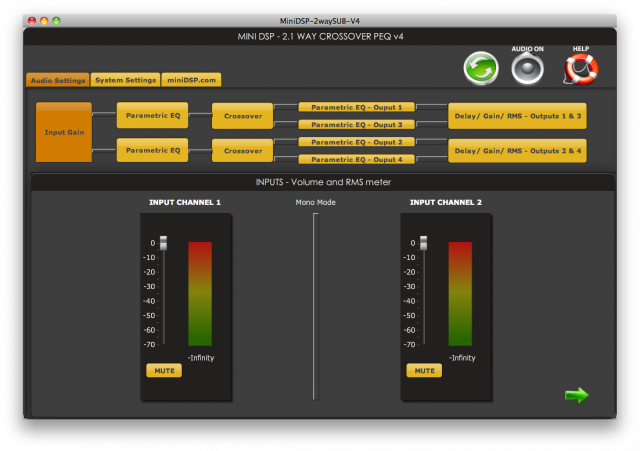
Each of the blocks labeled “Input Gain,” “Parametric EQ,” “Crossover,” and so on, can be clicked on to display the settings screen for that function. Try clicking on them to get a feel for the parameters you can set.
Click on the Sync button (the green one with two arrows on it). After a second or two, you will see a screen asking if you want to connect with the miniDSP – the first time, you will want to select the Update and Synchronize option; thereafter, this option become just Synchronize. After few seconds, you will see a message saying that the miniDSP has successfully synced, and the Sync button will now be grayed out. What this means is that any changes you make in the miniDSP UI (user interface) on your computer are immediately relayed to the miniDSP board over USB, with the audio processing updating in real time. It’s pretty cool.
Note: if the above steps resulted in a message stating that the connection to the miniDSP failed, then you will need to stop and trouble-shoot. If you are using a USB extension cord, remove that and try again. If all else fails, you may need to contact miniDSP directly for technical support.
2. First audio steps
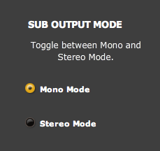
Now that you have the miniDSP “synced,” let’s set it up to work with the mains and sub by setting a crossover. Remember that the amps are all still turned off! For the moment, let’s set the crossover point at 80 Hz. First, since we are using a single sub, click on the System Settings tab and verify that Sub Output Mode is set to Mono. This is because we only have a single sub, so the low-frequency content from both channels will go to that one sub:
Then click on the Audio Settings tab again, where you will see the processor block diagram:
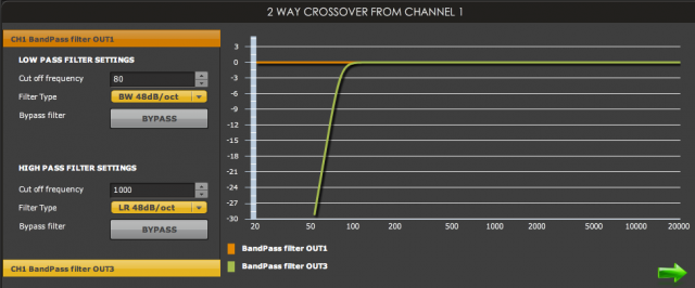
Click on the top Crossover block. You will see a screen like this:
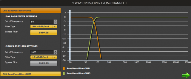
Use the settings panel on the left to make the following settings:
- Lowpass filter cut-off frequency set to 80 (Hz)
- Lowpass filter type set to “BW 48dB/oct” Butterworth 48dB/octave slope
- Highpass filter bypassed (the Bypass button is grayed out)
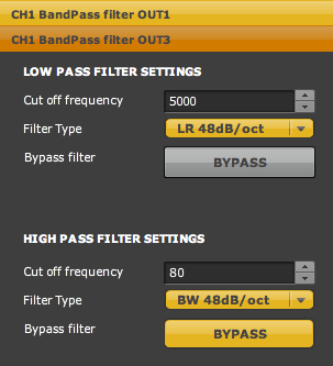
Then click on the button labeled CH 1 Bandpass Filter OUT3 and make the following settings:
- Lowpass filter bypassed (the Bypass button is grayed out)
- Lowpass filter cut-off frequency set to 80 (Hz)
- Highpass filter type set to “BW 48dB/oct”
Now repeat these settings for the other crossover (the lower one in the block diagram).
We have just set a steep crossover between the sub and the mains at 80Hz. Later on we will determine the best settings for this crossover. One of the great things about using a DSP-based unit like the miniDSP is those steep crossover slopes. A 48 dB/octave crossover means that the sub passes very little signal at frequencies that would enable the sub to be localised. In addition, many subs have “breakup” or resonant modes above the subwoofer range, and the steep crossover slope ensures that very little signal at those frequencies gets to the sub.
For the mains, the steep crossover slope ensures that frequencies below the crossover point are removed very rapidly. Inevitably, the excursion of a woofer increases greatly at low frequencies, and higher cone excursion naturally leads to higher distortion. If the mains are small monitors with small woofers, this can pay large dividends in reducing distortion from those woofers. An active crossover at a 48 dB/octave slope will reduce distortion much more than can be achieved with passive (either line-level or speaker-level) crossovers at those low frequencies.
The miniDSP allows you to set a range of less steep crossover slopes as well. Butterworth slopes of 6 dB/octave, 12, 18, and so on up to 48 dB/octave are available, and Linkwitz-Riley slopes at 12, 24, 36, and 48 dB/octave are available. The lower the slope, the less rapidly frequencies above or below the crossover point are attenuated. (The difference between Butterworth and Linkwitz-Riley slopes is a technical one – perhaps a topic for a future tutorial.)
Now, with the basic crossover configuration done, you should be able to verify by ear that only low frequencies pass to the sub, and all but the low frequencies pass to the mains. To test this, set your preamp volume to minimum and start playing a known track with low bass on it. Turn on the subwoofer amp (only) and slowly turn up the volume. Since only the lowest frequencies are playing, it will naturally sound very “muffled,” but if you play a track that you know has a very low bassline (some electronica for example) you should be able to hear that bassline.
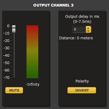
Now turn off the sub amp and turn on the main amp. The mains should sound OK, but with some bass weight missing. At this point, turn the sub amp back on. You will probably need to adjust the relative levels of the mains and sub channels. Click on the Input Gain block and mute Channel 2. Then click on the Delay/Gain/RMS block for output channels 1 and 3, and adjust the level of output channel 1 down (to reduce the sub level) or of output channel 3 down (to reduce the mains level). For example:
For now, just do this adjustment by ear. Then apply the same setting to the other Delay/Gain/RMS block, and go back to the Input Gain block and un-mute Channel 2. Congratulations! You now have miniDSP running a crossover between your mains and sub. But, we haven’t really tapped the power of the miniDSP yet! To proceed further, we will need to do some measurements.
3. Doing in-room measurements
Doing acoustic measurements is a lot easier than it used to be, with free software available and relatively inexpensive microphones and USB-based computer interfaces. While purchasing the hardware items for acoustic measurement will add a little more than promised to the cost of this project, consider that you can use them for countless calibration and acoustic measurement uses in the future…
Here is a block diagram illustrating the key items that will be needed and how they connect into the system:
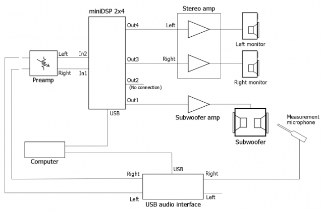
Figure 2. USB-based measurement system
Now, one good thing about this kind of setup is that you can try out the software before spending a cent! There are a number of measurement programs available, but a good choice to start with would be Room Eq Wizard (REW), as it is free, well-documented, runs on both Windows and Mac, and has an active support forum. (You will need to register to download REW. I used V5 Beta for this article, and all screen shots in this article are from that version.) After installing it according to the instructions, configure it to run a measurement sweep using the built-in microphone and speaker of your computer. The result will be fairly meaningless, but you will be able to do enough to learn the basics of using the program.
If you decide to go ahead, you will need a better microphone, and a way to get it connected to your computer. I use an Earthworks M30, but it is getting up there in price for a project such as this. A popular inexpensive option for the microphone is the Behringer ECM8000. There is significant variation between cheaper microphones, so you may wish to pay a little extra to get one that is “calibrated.” A calibrated microphone comes with a file that is loaded into measurement software such as REW to compensate for the microphone’s non-flat response. Some possible sources are IBF Acoustik and Cross Spectrum Labs.
Note also that a measurement microphone is needed – microphones designed for vocal or instrumental pickup are not suitable for this purpose. You will also need a microphone stand – you cannot hold a microphone by hand to perform measurements. Any cheap adjustable stand (with a boom arm) from a music supply store should suffice.
To get the measurement signal out of your computer into your preamp and the signal from the microphone into the computer, a good option is a USB audio interface made for recording. I use an Edirol UA-25EX, but cheaper devices are available – please feel free to make a recommendation in comments at the bottom of this article. You will need to follow the instructions for your device to get the drivers installed onto your computer, and then connect the interface to your preamp as shown in Figure 2 above.
Another option is to use a standalone microphone preamplifier, and the line in and line out jacks on your computer.
To proceed, we will need to set the miniDSP so that only Channel 1 is playing, and only the sub channel is playing, without any crossover:
- Click on the Input Gain block and mute Channel 2
- Click on the Delay/Gain/RMS – Outputs 1 & 3 block, and mute output channel 3
- Click on the top Crossover block, and select Bypass for the Channel 1 output. It should look like this:
Once you have things configured, you can start your in-room measurements.
Warning: test signals are an unnatural load for loudspeakers, and you can damage loudspeakers if you are not careful. Keep the signal level low and be careful not to overdrive the loudspeaker at low frequencies. In the following, I start my sweeps at 10 Hz, because my subs are sealed and I know they can “handle” it. Smaller ported subs may have a very high excursion if driven at those frequencies, so you may wish to start your sweeps at 20 or even 30 Hz, depending on their size.
With the warning out of the way, I set REW to use the USB interface for audio input and output, and run a measurement sweep from 10 Hz to 1 kHz. Figure 3 shows the plot made with the Earthworks M30 microphone (blue), and with an uncalibrated Behringer ECM8000 (green), placed at the same position in the room. In this plot, the ECM8000 reads about 9 dB low at 10 Hz; 3 dB low at 20 Hz; 1.1 dB low at 30 Hz; and 0.6 dB low at 40 Hz. As noted above, a calibrated microphone should be used for best results.
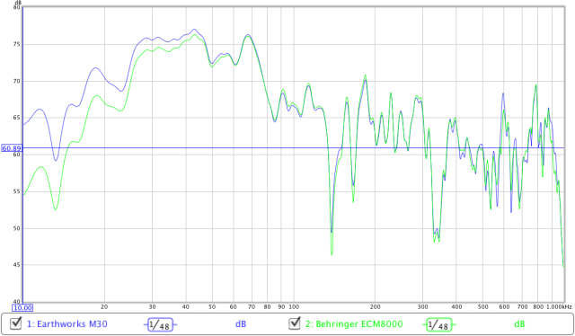
Figure 3. Earthworks M30 compared to Behringer ECM8000
One final thing that needs to be introduced here is the concept of “smoothing.” In REW, you can apply different levels of smoothing to the measurement curves, with less smoothing (1/24 and 1/48 octave) showing more detail in the measurement, and more smoothing (1/3 octave, for example) enabling more general trends to be seen. Here is an example illustrating three different levels of smoothing, where purple is 1/48 octave, blue is 1/12 octave, and green is 1/3 octave:
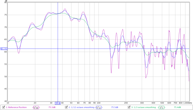
Figure 4. Effect of smoothing
4. Measuring the subwoofer
To get an understanding of the response of my subwoofer in this room, I performed seven measurements. One with the microphone at the “reference” listening position. Then two more with the mic moved left and right 50 cm, then two more with the mic moved forwards and back 40 cm, and finally two more with the microphone moved up and down 30 cm. These seven measurements, shown in Figure 5, cover the region in space over which I would like to optimize the subwoofer response.
(Note: Remember that, at this point, we are still measuring only the sub, and without any crossover applied to it.)
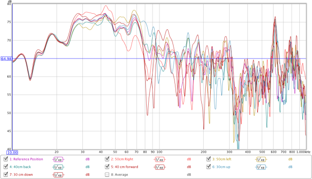
Figure 5. Measurements at seven mic positions
Viewing these measurements, we can see that, up to about 70 Hz, the measurements are fairly consistent over this region in the room. There is a lot of variation in the 80-100 Hz region. This variation cannot be corrected by equalization, and should if necessary be addressed by other means, such as changing the location of the sub, by deploying multiple subs, or by acoustic treatments (although at this frequency, they can be expensive).
Note that these measurements all use 1/48 octave smoothing. For performing subwoofer equalization, we need to see some “detail” in the measurements. The next question is what measurement do we equalize? An average is a reasonable choice, and REW allows us to create an average reading of this set of measurements, which is shown in Figure 6 in blue, along with the reference position measurement in red. In this case, the average is not very far from the reference – this is good, as it means that I can just redo a measurement at the reference position to see if an adjustment made with the miniDSP has had the desired effect. I don’t want to redo measurements in multiple microphone positions each time I make an adjustment!
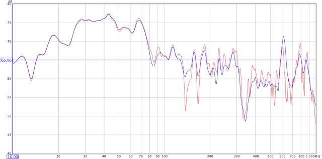
Figure 6. Reference listening position (red) versus averaged response (blue)
5. Applying equalization
The miniDSP has a set of six filters on each output channel, and these are what are going to use to accomplish our subwoofer equalization. To see the filters, click on the Parametric EQ – Output 1 block. The parameters for each filter are set one at a time by selecting EQ1 through EQ6 at the left of the pane. I set the parameters for EQ1 as shown in this diagram:
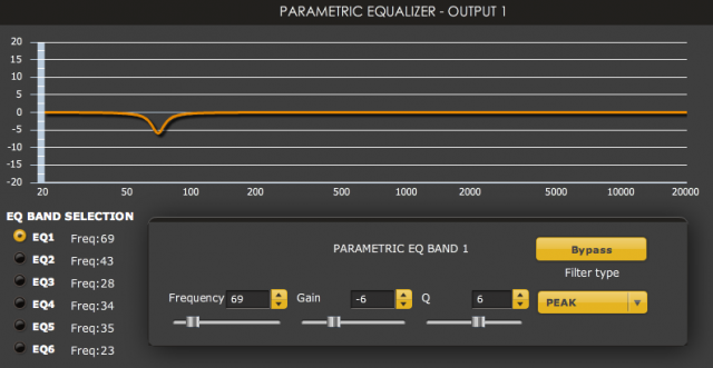
Screen 7. Single notch filter at 69 Hz.
What do these parameters mean?
- The filter type is Peak. This is the type of filter to select for creating a notch or a boost centred at a particular frequency.
- The Frequency is the centre frequency of the notch or boost.
- The Gain is the amount by which the centre frequency will be cut (if negative) or boosted (if positive).
- The Q determines the “sharpness” of the filter. A higher Q leads to a narrower notch or peak. In general, use the lowest Q that you can to achieve a good result.
Here is the measurement of the subwoofer with this filter in place (in blue), along with the original measurement (in red):
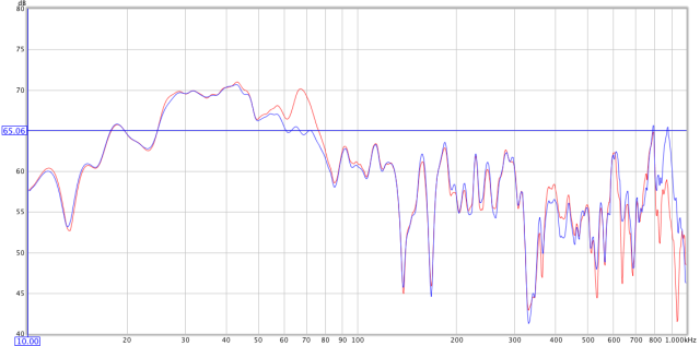
Figure 7. Effect of the 69 hz notch filter
You can see that the filter has dropped the peak down. Note that you can never get it perfect and it may take a few attempts to arrive at a good compromise. Bear in mind also that there is some interaction between the filters, so some re-adjustment of the filter parameters will be needed as additional filters are added.
I repeated this process to address the broad peak in the 25 to 50 Hz region. From looking at the curve, it appears to be the sum of peaks at around 28 Hz and 43 Hz, with perhaps something else filling in the middle. Acoustic modeling of my room is consistent with this, so I ended up using three notches, at 28, 34, and 43 Hz.
Finally, with some trepidation, I added a boost at 23 Hz. This frequency corresponds to the primary mode along the length of my room, and a relatively small amount of boost of 4 dB with a Q of 4 was enough to bring up that dip. In general, large amounts of boost or high-Q boost filters should be avoided. As an exercise, it was useful to put this filter in, but I may experiment in listening tests with reducing the amount of boost here or simply turning it off.
After all that, here is the result showing the measured response of the subwoofer at the reference listening position (green) compared to the original response (red):
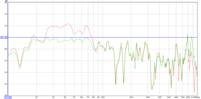
Figure 8. Before (red) and after (green) equalization, at the reference listening position
Here is the complete equalization curve for the subwoofer, with all filters in place:
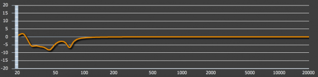
Note that applying equalization uses up “headroom” in your system. With a variation of 10 dB or so in this curve, my subwoofer amplifier will be using up to 10 times more power at some frequencies than it will at others, given the same level coming off the CD. If you end up with a curve with more variation than this, it may be worth trying different locations for the subwoofer.
I then ran another series of sweeps in the seven different microphone positions to confirm the results. These are shown in Figure 9. Compared to Figure 5, you can see that overall the response is now much flatter than it was without EQ, but the EQ has not of course been able to address the variation in the curves in the 80-100 Hz region. While there are visible resonant peaks higher in the frequency range (for example, at 600 Hz), these are far enough above any likely crossover point that we can ignore them.
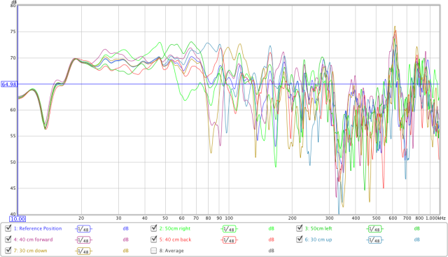
Figure 9. Seven listening position measurements, after EQ
6. Integrating the mains
Now, we want to add the main speakers back in and fine-tune the crossover settings. Since we have the audio for the mains being sent through the miniDSP anyway, it is tempting to use the miniDSP for “room correction” on the mains as well. Above subwoofer frequencies, though, things get a little trickier, and acoustic treatment should be done first or in conjunction. So I’m not going to do that for now, but there is one thing that I would like to do to the mains, which is to perform “baffle-step compensation.”
The term baffle-step loss refers to the apparent drop in output level as the sound wave transitions from a hemispherical wave (at higher frequencies) to a spherical one (at lower frequencies). The frequency of this transition is determined by the width of the baffle (of a boxed loudspeaker). Many speakers have “baffle-step compensation” for this effect built into their crossover. Mine do not, so I’d like to do it in the miniDSP. In your case, you may find that your speakers need some compensation, or you may even find that your speakers are over-compensated for your listening room – in which case you can “undo” some of it with the miniDSP.
We will need to measure the mains to determine how much compensation to apply. Measuring the mains can also help us to choose a good crossover point.
Warning: test signals are a good way to damage your loudspeakers. Start with the level in this test very low, and only increase it to the point where you can get a useful measurement. We do not need a lot of accuracy here. If your mains are ported, you may wish to start the sweep only at a frequency a little below the specified -3 dB frequency of your speakers. If this makes you uncomfortable, you may wish to continue but with the highpass filter (crossover) still in place, or to simply skip this section.
To proceed, we will need to set the miniDSP so that only the right monitor is playing, without any crossover:
- Click on the Input Gain block and check that Channel 2 is muted.
- Click on the Delay/Gain/RMS – Outputs 1 & 3 block, mute output channel 1, and un-mute output channel 3.
- Click on the top Crossover block, then click CH1 Bandpass filter OUT3, and select Bypass for the highpass filter.
Then perform a sweep measurement from your chosen starting frequency up to 2000 Hz. I do this with the microphone about 50cm from the speaker – this ensures that we can see the baffle-step loss and the low-end response of the speaker, while not allowing the room to totally swamp the results. (For the technically inclined: I know this is not the best way to do this, but it’s easy and is good enough to get us into the ballpark.) Applying a 1/3 octave smoothing enables the general trend to be seen. The red curve here shows my result:
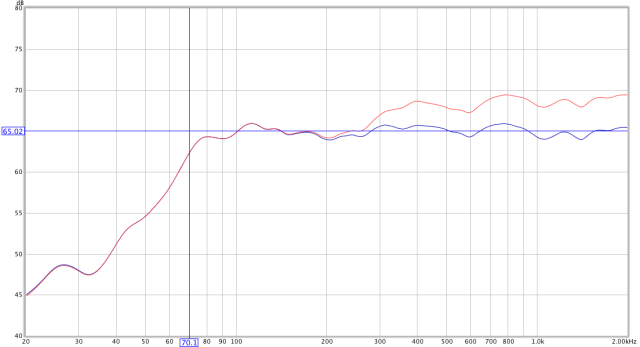
Figure 10. Right monitor, before and after baffle-step compensation
From this measurement, we can see that the mains naturally roll off with a -3dB point of around 70 Hz. We can also see that the response rises 4 to 5 dB between 250 and 800 Hz. Some more specifics on each of these.
- My mains are sealed monitors, with a calculated -3 dB point of around 80 Hz. Sealed speakers roll off at around 12 dB/octave, which (allowing for some room gain at low frequencies) is about what we see here. Ported speakers will roll off at 24 dB/octave, at (most likely) a lower frequency.
- My mains have a baffle width of around 7 1/2 inches, with a theoretical center frequency of the baffle step loss of around 600 Hz. The theoretical baffle-step loss is 6 dB, but in general it is less than that “in room.”
The measured results are thus reasonably close to the theory. Let’s perform the baffle-step compensation first. To do this, I use a High-Shelf type of filter in the Parametric EQ – Output 3 block, with a centre frequency of 500 Hz, a gain of -4 dB, and a Q of 1.5. Here is the miniDSP parameter screen for this filter:
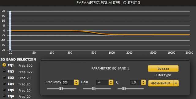
With this filter in place, the measured response is shown in blue in Figure 10 above.
For the crossover, let’s start with a “textbook” approach. There are two key choices. One is that we use the speaker’s natural low-end rolloff as part of the crossover; the other is that we don’t, in which case the crossover point should be well above the speaker’s -3 dB frequency. So, in this case, I’ll choose a 70 Hz crossover frequency. This is convenient, as it helps to avoid the messy 80-100 Hz region of the in-room subwoofer response that we can see in Figure 9 above.
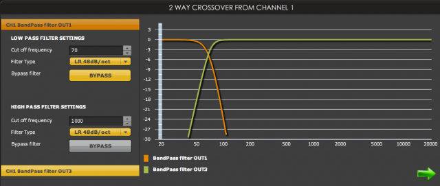
Since the mains roll off at 12 dB/octave, I choose a 36 dB/octave slope on the high-pass filter for the mains, giving a total rolloff of 48 dB/octave. To match this, I set the lowpass filter for the sub at 70 Hz, 48 dB/octave. Here is the settings screen:
Now, un-mute the sub channel and run a measurement with the microphone back at the listening position. Here is my measurement, showing the response of the sub (blue), the right monitor (green), and the two of them together (red):
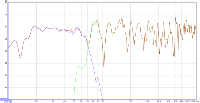
Figure 11. Right monitor and sub
As you can see, the level is slightly mismatched – this is easily adjusted in the Delay/Gain/RMS block. You can clearly see the effect of the steep crossover slopes, but the dip at the crossover point indicates a phase mismatch.
Phase correction
Correcting a phase mismatch at the crossover point can be a little tricky. One approach is to simply try adjusting the crossover types and slope. A second is to use the Invert and Delay options in the Delay/Gain/RMS block. To start with, use the Invert button for output channel 1 to see if the problem is reduced.
The miniDSP also provides up to 7.5 ms of delay on each output. This corresponds to a bit over half a wavelength (i.e. polarity inversion) at 70 Hz, so there is plenty of phase shift that can be accomplished here. If your sub is further away from you than the mains, try delaying output channel 2 first by a millisecond at a time to see how the response is affected. If that doesn’t work, set the delay on channel 2 back to 0 ms and try delaying channel 1 instead.
The other side
So far, we have only done one channel! What we now need to do is copy all of the crossover and filter settings from the channel we have been working on to the other channel. I found the easiest way to do this was to just write them down on a piece of paper, then enter them into the other channel, rather than constantly switching back and forth between channels.
Having copied the settings, we can re-measure through the other channel. You may find that the two channels differ from each other, especially around the crossover point. Some adjustments may be needed, but I would suggest not changing the two channels too far from each other – you may need to just choose a reasonable compromise. Here are my results at the reference listening position (with 1/3 octave smoothing):
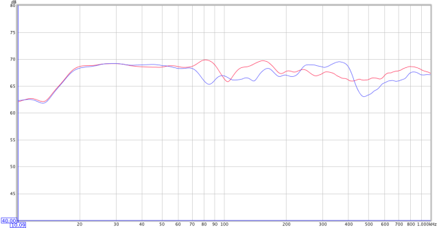
Figure 12. Response of left (blue) and right (red) channels in-room
In my case, the left channel proved to be more “difficult” than the right. To do better, I will need to reposition the monitors to provide a more even acoustic response from both channels. I’d also like to try moving the sub and seeing if I can raise the crossover point to around 100 Hz, to reduce the excursion on the monitors.
Wrapping up
There is one final setting in the miniDSP that you may like to employ. If you have a ported sub , a highpass filter on the sub channel may be beneficial to ensure that the driver does not “bottom out” at high volumes. The reason for this is that the excursion of the driver in a ported sub increases very rapidly below the port tuning frequency. I won’t go into how to determine an optimum frequency here, but try setting it at 30 Hz with a 48 dB/octave Butterworth filter.
Remember also that equalization is not a panacea. If you are unable to get satisfactory results, or have a very “wild” equalization curve on your sub, then you may wish to experiment with subwoofer location to get a better in-room response before applying equalization.
Once you’re happy with the settings of the miniDSP, use the System Settings tab and save the configuration onto your computer in a location where you will be able to find it again. Then turn off all power amplifiers, and disconnect the miniDSP from your computer. Connect a USB charger to the USB port, or, if you ordered the optional DC power connector, connect a DC power supply of between 4.5 and 24 V. You should never power up or power down the miniDSP with your power amplifiers turned on. Turn the power amplifiers back on, put on some of your favourite music, and sit back and enjoy the fruits of your labour!
Acknowledgements
My thanks to those who made comments that improved this article: Nyal Mellor, Patrick Dillon, and Tony Rouget (of miniDSP). And also a special thanks to Terry Jones who introduced me to REW and showed me why I needed to learn more about acoustic measurements.


Fantastic read! Well written. A must read for all enthusiasts trying to integrate subs into their audio system.
Very informative, John! After reading this, I plan on getting a MiniDSP very soon.
Thanks, I was planning on using the BFD for my EQ but your step-by-step user guide has me looking at the MiniDSP now!
Thank you for this guide.
Thanks for the great write replete with pictures and diagrams. I too was going to pick up a BFD, but again after reading this the miniDSP is on the short list.
What can I say? Amazing!!!
I already have a MiniDSP based active system and learned a lot from this article.
Thanks
I have recently purchased a miniDSP and have been using REW for about 4 weeks and both are excellent products. I have a Dayton Audio calibration mic , balanced USB preamp and both mic and soudcard calibration files have been added. I have generated a Pink Noise ( periodic noise ) CD so I can test with the RTA ( with PN full range ) or a log sweep.
Test A: Test with log sweep.
Test B: Test with RTA and PN
Each test gives very different results above about 2 kHz.
Is there any reason for this. Some articles I have read suggest Pink Noise ( periodic noise ) should be used for room EQ and not log or linear sweeps.
Any advice is appreciated.
Thanks,
Roger
Toowong Australia.
Great article John. I may be getting a MiniDSP in the near future.
John
There is a good thread on multi-channel DSP/DRC at computeraudiophile.com I posted a linl to your article above. You may find it interesting and I know you could contribute…
http://www.computeraudiophile.com/content/Room-correction-Stereo-Surround#comment-131180
Thanks for a good article and the links to your other work!
–Caleb
I have recently purchased a miniDSP and have been using REW for about 4 weeks and both are excellent products. I have a Dayton Audio calibration mic , balanced USB preamp and both mic and soudcard calibration files have been added. I have generated a Pink Noise ( periodic noise ) CD so I can test with the RTA ( with PN full range ) or a log sweep.
Test A: Test with log sweep.
Test B: Test with RTA and PN
Each test gives very different results above about 2 kHz.
Is there any reason for this. Some articles I have read suggest Pink Noise ( periodic noise ) should be used for room EQ and not log or linear sweeps.
Any advise is appreciated.
Thanks,
Roger
Toowong Australia.
Hi Roger, I’d be more inclined to trust the sweep. One thing to check would be that you have enough signal to noise ratio, RTA tends to pick up noise more easily. I don’t know why anyone would suggest pink noise over a sweep… could you provide a link? I’ll try running a comparison in the next day or two and update.
Hello John,
Thanks for a very informative article. Is it possible to connect and integrate a sub to my system connecting JUST the input of the 2×4 miniDSP to my AVR (Marantz SR 7008-Audyssey XT32 enabled) sub output.. The output of the miniDSP would then go to the input of my sub.
I would then use REW in conjunction with the UMIK1 to measure the system. Also I’m thinking that I might just wait for the nanoAVR to be released for better integration. As you might deduce I have no external amps so I need to be able to use just the AVR with a miniDSP product as I would use no pre amp—–>miniDSP—–> amp .
Thanks,
Kirk.
Hi Kirk, thanks for the kind comment. Yes, you can use a miniDSP 2×4 just on the sub line between the AVR and the sub. I had one running that way for a while. There are some limitations i.e. you have to work with what the AVR does as the high pass and low pass filters but I didn’t have too much trouble getting good integration. Having said that… well, I would wait for the nanoAVR, it will give you full control over all channels by the looks of it. Price hasn’t been announced yet I don’t think.
Hi John,
Thanks for your consideration. I think I will wait for the nanoAVR as you advise. I did contact the people at miniDSP and they indicated that the nanoAVR might be released around February-March timeline.
Regards,
Kirk.
Hi John.
Thanks for a great and informative article.
My set up is a little different from those shown.
The feed from my PC goes to an external DAC (by Toslink) and then to an integrated amp from which the pre/subwoofer out feeds a subwoofer via a dual RCA cable and the normal speaker outs feed my stereo speakers .
I am thus wondering if I can place a miniDSP 2×4 in this circuit after the DAC with miniDSP feeding the subwoofer direct and feeding the speakers via the integrated amp ?
Any advice would be very much appreciated.
Hi Alex, if I understand your configuration correctly, it won’t work. You would need to put the miniDSP 2×4 “after” the amplifier. (The issue is where volume control takes place.)
HI,
Thanks for the reply.
I must admit that I’m still confused though because if the minidsp is placed after the amp how would I feed my speakers? I don’t think it has any speaker out terminals does it ?
At the moment my integrated amp feeds the subwoofer from the amps pre/subwoofer out terminals and also my main speakers via the normal speaker outs with the integrated amp fed from a DAC.
One of the functions I would like the minidsp to perform is to split the signal so that the subwoofer only receives the lowest frequencies and the main speakers only receive the higher frequencies.
I imagined the set up would be DAC to minidsp and then minidsp driect to subwoofer (after frequency filtering) and minidsp to integrated amp (after frequency filtering) to feed the main speakers these filtered frequencies.
In effect it is your Fig 1 but instead of the Preamp would be a DAC. So I am really asking if I can substitute the Preamp with a DAC ?
I hope this clarifies my problem and once again any advice would be most welcome and appreciated.
Regards Alex.
“In effect it is your Fig 1 but instead of the Preamp would be a DAC. So I am really asking if I can substitute the Preamp with a DAC ?”
Hi Alex, you can IF your DAC (or the digital source in front of it) has a volume control, and you are able to leave the volume control on the integrated amp at a set level (say full up, so it’s acting like a power amp).
Sorry for the confusion, when I said “after the amp” I should have said “after the volume control”.
Another option to consider is the new unit announced by miniDSP at CES, which has USB audio streaming directly in.
Hi John – a very useful tutorial, even though I am a complete novice, I managed to get my MiniDSP working on the first try simply by following your instructions.
One issue I came across though is that the output volume is significantly reduced when connecting through the MiniDSP vs. directly. This is using the same source and volume settings on the main amp and the sub.
Is this how it should be?