Assembling the Bugle 2 phono stage
Last year, I wrote an interview with Jim Hagerman about the Bugle 2 phono preamp that he (successfully) launched on KickStarter. As a “backer” of his campaign, I did of course receive the Bugle 2 kit in the mail after the campaign concluded. I decided to do a short photo essay on assembling the Bugle 2.
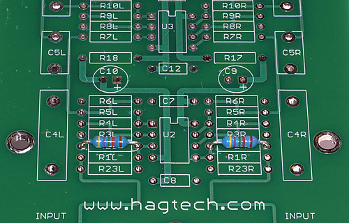
The packing envelope contains the Bugle 2 circuit board inside the case, a bag of parts, a 24V wallwart, and the assembly manual with schematics and board layout:
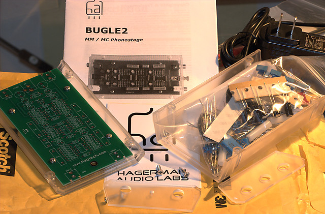
There are a lot of parts in that little plastic bag… don’t lose any!
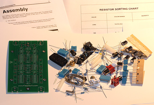
Solder is included – a nice touch. You will find it easier to assemble the Bugle 2 if you don’t have to do a hunt-and-peck for every part. Here I’ve organized the parts by type. The resistors are organized further by the first digit – in this kit, resistor values start with the digits 1, 3, 4, 6, and 8.
Now we can get started with actual assembly. The resistors go first. Here’s the proper way to bend the leads so you can load the resistor into the board:
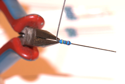
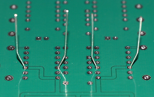
With both leads bent, load the first pair of resistors into the board:
On the underside, maybe this is old-school but the way I was taught to do this is to bend the leads so that there is physical contact (not just solder) between the lead and the hole, like this:
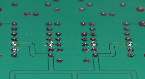
You will now need to use a fine-tipped soldering iron to solder the leads. You’ll notice that there’s a very fine division between the holes and the surrounding ground plane, so be careful and don’t go splashing solder about the place. The Bugle 2 might not be the best choice for a very first project. After soldering, clip the leads short:
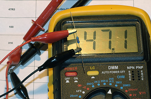
You can then keep going, methodically and carefully. By the way, I always check resistors with a multimeter before loading them, it’s such a major pain to rework a loaded circuit board that this is time well worth spending. And you have to pick the resistor up somehow anyway, so I use clipleads attached to the meter for that:
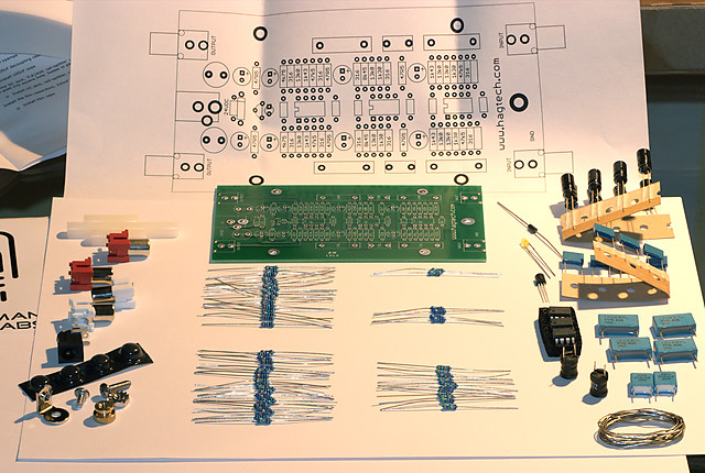
After loading all resistors, the board looks like this:
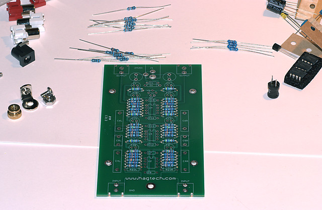
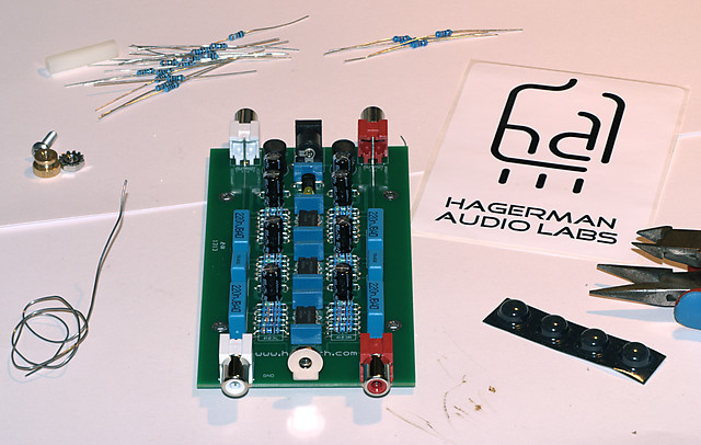
There are some leftover resistors because the Bugle 2 comes with all resistors needed for three different gain options – 40, 50, and 60 dB. Here’s the board after loading all of the remaining components:
After screwing the board back into the enclosure and a quick flight-check, here is the Bugle 2 in action!
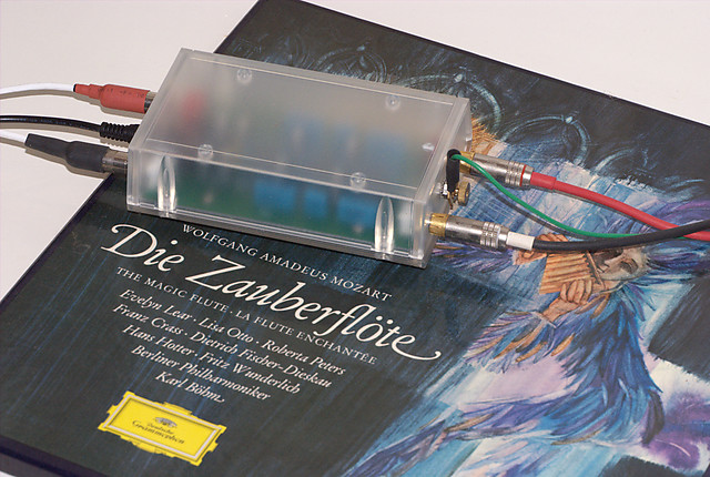
OK, I guess that picture is not very exciting, but it worked first go and it does sound good. I’m not exactly an accomplished vinyl aficionado and still have lots of work to do to get my ‘table set up properly, but I’m pleased with the Bugle 2, for a couple of evenings of leisurely assembly.


Hi John
I had the same excitement in mind when I ordered the Bugle 2 this year 2014.
After building DYI and Heathkit projects in my earlier years and I thought this would be a snap.
WRONG Right channel has very low gain in relation to the left. I’ve contacted Jim Hagerman a number of times, looked at my assembled project pictures and rebuilt/soldered the unit and I am STILL left with this problem. Any suggestions?
Signed
Bugle Blues 2
Hi Bill,
Were you able to resolve this issue? I’m experiencing the same audio imbalance with mu bugle2. Please share onhow you solve it. Thanks.
To Bill: I built a Bugle a few years ago. With all those resistors grouped so close together, it would be easy to overflow solder from one pad to the next and hard to detect it visually. If you haven’t done this yet, get out your VOM meter and verify each resistor value plus proper continuity between parts based on the schematic.
If that doesn’t turn up the problem, have someone else look at your assembly. Even if they don’t know electronics, you can quickly show them how to measure with a VOM and read the schematic. A fresh set of eyes may find something you missed. It’s happened to all of us.
In April 2014 I purchased one assembled for $189.00US to include postage. I expect I may have paid more than you guys because it was assembled but worth it to me. I bought it upon an audition at a friend’s house in a quality system.
This is a fine little phono pre. I cannot find a fault with it and is superior to what it replaced. I can highly recommend it and do! Cheers.
This is sonically a good kit, but the board *is* extremely tight in design and its having single-push-through holes with tiny rings rather than a printed circuit board with traced metal makes this the sort of board usually soldered by robots in the “real” world. It takes a pin-point sharp soldering tip and it is easy for solder to creep into an extra hole, and once it is there, tricky to remove. Be artful & patient when assembling this. I have spent many hours soldering in my life and took it for granted this this would be a fairly ordinary job. It is actually tricky if you are used to something like guitar-amp kit PCBs.