A tour of the miniDSP 2×8
Shortly after I completed my last article on my 4-way open-baffle prototype using the miniDSP 2×4, the folks at miniDSP dropped a surprise into their online store: a two-input, eight-output DSP card called the “miniDSP 2×8.” I have to admit that this stopped me in my tracks. I had to think for a while about where I was going with my open-baffle project… should I make a move to the new 2×8 card, or continue with the existing pair of 2×4 boxes? It didn’t take too long to tally the advantages of the new card:
- All inputs and outputs can be used balanced or single-ended
- The internal processing rate is 96 kHz (up from 48 kHz)
- No need to swap the USB cable to adjust settings on the other channel
- Capable of up to 4 input and 10 output channels (more on that below)
All in all, it added up to a compelling proposition. So, I ordered one, and sat down with my laptop and the downloaded software to learn its ins-and-outs. I will use my 4-way open baffle prototype as the working example, with my first task being to “port” my current system across to this new hardware.
The Software
I started by transferring across my settings from the dual 2×4 setup to the “4×10 Xover” plugin for the 2×8 board. For those not familiar with the miniDSP nomenclature, a “plug-in” is the software that runs on your computer and provides the user interface that you use to configure the miniDSP. It communicates with the miniDSP hardware over USB. Once the miniDSP hardware is configured, you can disconnect the USB – you don’t need to keep the computer connected to play audio.
The next thing to clear up is the name of the plug-in. It is called “4×10” because – when the digital inputs and outputs are counted – a total of four input channels and ten output channels are supported. The digital input and output channels are provided by S/PDIF or TOSLINK connections on the miniDIGI daughter board, which is an optional purchase with the 2×8 board.
Why would you want ten output channels? Well, you don’t have to use them all, but having them does provide some interesting flexibility. In my main system, I will be configuring six output channels for the main open baffle panels (woofer, midrange, tweeter), and three or four as output channels for subwoofers.
The “architecture” of the 4×10 plug-in is different from the plug-ins for the 2×4 board. It is more complex, but easy enough to navigate once you understand it. I’ve drawn the overview block diagram in Figure 1 below, and will cover each of the major blocks in the following sections.
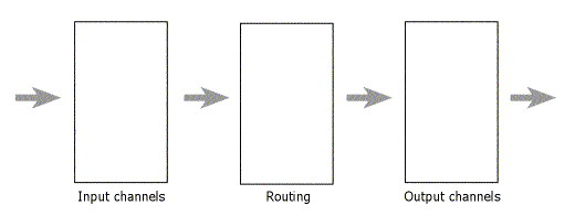
Figure 1. miniDSP 4x10 block diagram
Input channels
Let’s start by setting up the input channels. Clicking on the Input button displays the screen shown in Figure 2 below. Each channel has a label that can be edited so that you can give each channel a name that is meaningful to you. This is a very handy feature, although you are limited to eight characters – I have labeled mine “Analog L,” “Analog R,” “Digi L,” and “Digi R.”
The controls on each channel, from top to bottom, are:
- A Monitor button that brings up a live meter for that channel (you can monitor the signal level on only one input channel at a time)
- An input level adjustment (attenuation only)
- A button to bring up the parametric equalizers for that input channel
- A Mute button
(Click on this or any screenshot in this article to bring up a larger version.)
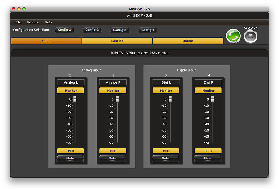
Figure 2. mini DSP 2x8 Input Screen
Clicking on the PEQ button brings up the equalization screen shown in Figure 3, as an overlay in the main window. There are five parametric equalization filters for each input channel, each of which can be set to a boost or notch filter, a low-shelf filter, or a high-shelf filter. If you are familiar with the miniDSP lineup, you’ll notice this is one less than available with the plug-ins for the smaller board – this is simply a matter of how the finite processing resources of the DSP are allocated. I’m happy to trade off one EQ filter per input in return for the extra channels and the 96 kHz processing.
There is also a “Link Enabled” check box at the top left. In Figure 3, I have linked channel 1 to channel 3 – that is, the left analog and left digital channels. This means that identical equalization settings will be applied to both left channels. I have also linked channels 2 and 4, the right analog and digital channels. Each channel can be linked to only one other channel, so I still have to set up the left and right sets of input channels separately.
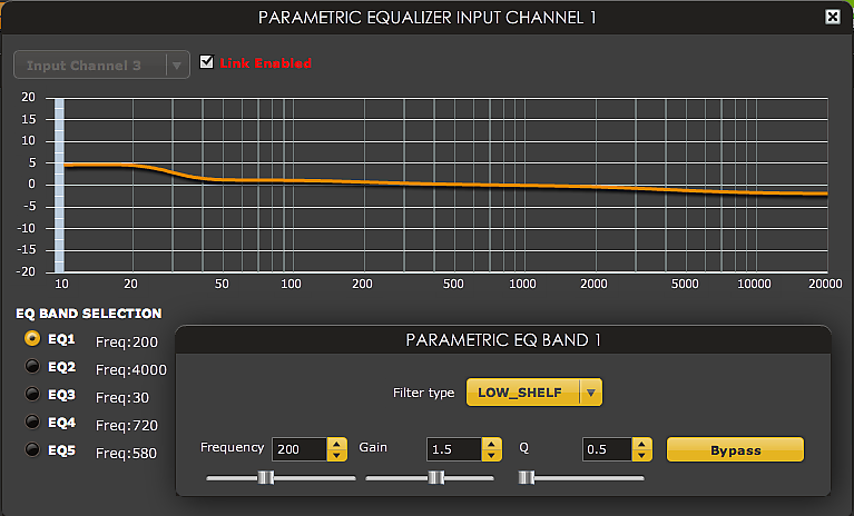
Figure 3. miniDSP 2x8 input channel parametric equalizer screen
Output channels
Next, let’s set up the output channels. Clicking on the Output button displays the screen shown in Figure 4 below. It looks a bit like a mixing console, with one “strip” for each output channel. A custom label can be set for each channel – I named mine “Sub L,” “Woofer L,” “Mid L,” and “Tweet L” for the left channel, and similarly for the right channel. With so many channels, this is a very handy feature! I have also labeled one of the digital outputs “Mono Sub” – for use as a very-low-frequency mono sub channel via a cheap DAC – and the other “Unused.”
The controls are fairly self-explanatory, with buttons to bring up the monitoring meter, the crossover settings, and the equalization settings. Each output channel has an attenuation slider, and buttons to invert the phase and to mute that channel. Finally, there is an entry box to set to the delay on that output channel, with up to 9 ms of delay available (per channel).
Note that the two digital output channels are not quite “equal” to the analog output channels, as they have no adjustable delay on them. This may limit their application a little. I plan to use one for a mono sub, so I will have to see whether placement, phase inversion, and EQ will be enough to get a good response.
Before moving onto the crossover and parametric screens, one more control to note is the “Master Volume” enable switch at the lower right. This is used to enable volume control of all channels with an external 10 k-ohm potentiometer.
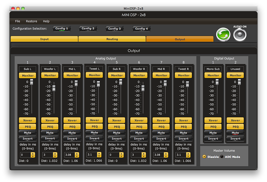
Figure 4. miniDSP 2x8 output screen
Clicking on the Xover button brings up the crossover settings for that channel, shown in Figure 5. The current channel is shown in orange, with three other channels shown in grey. (The selection of greyed-out channels seems to be based on the assumption that the 2×8 will be used for 4-way crossovers.) The crossover controls are the same ones that we are familiar with from previous miniDSP articles, with independent lowpass and highpass filters, each with a slope from 6 to 48 dB/octave and a choice of filter types (Butterworth, Linkwitz-Riley, and Bessel).
The crossover filters of each output channel can be linked to one other output channel. In my case, I have linked each set of left and right channels (for subwoofer, woofer, midrange, and tweeter).
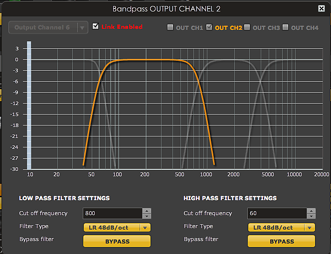
Figure 5. miniDSP 2x8 crossover settings screen
Next up is the PEQ screen, shown in Figure 6. As for the input channels, there are five parametric filters on each output channel. As I copied my settings over, in the cases where I had used six filters with the miniDSP 2x4s, I simply dropped the “least important” one for now.
The PEQ screen also allows channel linking. I have linked the left and right channels for the tweeter, and the left and right channels for the mid. I have not linked the left and right channels for the woofer and the subs, as – due to room effects – I use slightly different EQ settings on those.
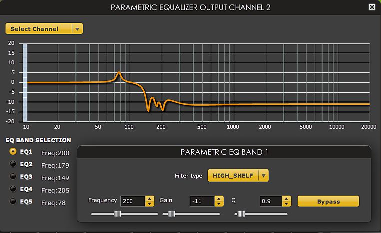
Figure 6. miniDSP 2x8 output channel parametric equalizer settings
Routing
With the input and output channels set up, we can define which inputs are sent to which outputs. Clicking on the Routing button displays the screen shown in Figure 7. Although it may seem complicated at first, the way it works is actually simple. You just need to remember two things:
- Each input channel can be sent to any number of output channels
- If more than one input channel is sent to an output channel, they are summed (added together)
This makes it easy to (for example) generate a mono subwoofer signal – something that required a special plug-in with the 2×4 series. You can send the analog and digital inputs to the same outputs, or to separate outputs.
In my setup in Figure 7, I have sent the analog and digital left channel signals to the four outputs for the left subwoofer, woofer, midrange, and tweeter; and likewise for the right channels. In addition, all input channels are sent to the digital output labelled “Mono Sub,” for use as a mono sub feed for very low frequencies. The final digital output is unused, so no input channels are sent to it.
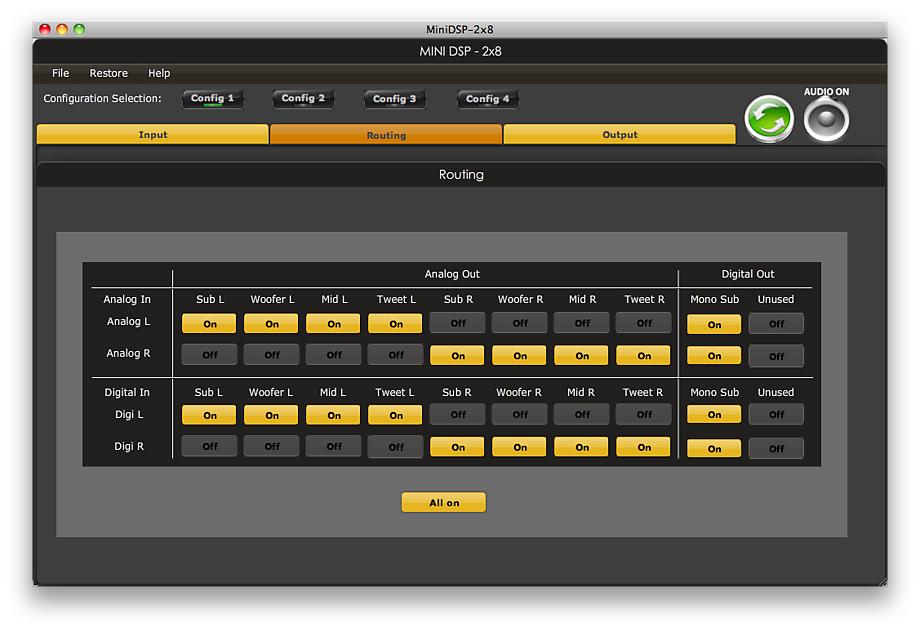
Figure 7. miniDSP 2x8 routing screen
Saving the settings
At this point, it’s a good idea to save all of the settings to a file. This is accomplished easily enough, by accessing the drop-down File menu at the top left.
Getting up and running
Now let’s take a look at the hardware. The miniDSP 2×8, with a circuit board size of 20 x 25 cm (8 x 10 inches), is not so “mini” any more. Unlike the miniDSP 2×4 modules I have been using until now, the 2×8 is a bare board, so some DIY work will be needed to install it into a suitable chassis. (Note that the original 2-in 4-out miniDSP is also a bare board – the nomenclature has become a bit confusing, with the “2×4” being the original 2-in 4-out board enclosed in a small chassis, and the “2×8” being a bare board.)
Powering up
The first task is to get the board powered up. Power must be supplied by a 12V DC supply – the 2×8 cannot be powered from USB. Any 12V supply that provides at least 1.5 A of current should work. For the moment, I am using a small 12V switch-mode power supply that I got on eBay for a few dollars, but there are lots of options. You could even power it from a 12V battery – while not stated in the datasheet, the miniDSP folks responded that supply voltages in the range of 9.5 to 14 V are acceptable.
Power is connected by wiring a pair of leads into the supplied Phoenix connector. Use a multi-meter to measure the voltage on the Phoenix connector before plugging it into the board, and check that the polarity matches that shown in the manual and also on the bottom of the board. Be warned that connecting the power backwards can damage your board! Then turn the power supply off, plug in the connector, and turn the power supply back on. You should see a blinking blue LED on the board.
USB connection
Now plug in the supplied USB cable and connect the other end to your computer. Pressing on the Sync button (green button with arrows) should bring up the dialog shown below. Pressing the “Synchronize Config” button downloads all of the settings into the 2×8 board. From then on, the board stays “synced” with the user interface – any changes made in the user interface are sent immediately to the board, so changes to the audio processing happen immediately.
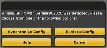
miniDSP 2x8 synchronization dialog
One interesting point to note is that up to four lots of settings (called a “configuration” in miniDSP-speak) can be loaded into the plug-in. Once they are all synchronized to the 2×8 board, you can switch between them with the buttons “Config 1,” “Config 2,” and so on, near the top of the main screen. This makes it easy to set up (for example) different sets of crossover points, slopes, and EQ for quick comparison. Or, if you don’t mind leaving a computer connected to the miniDSP, you could also use this for different subjective settings – for example, a setting for normal listening, a setting for late-night listening, and a setting for bass-shy recordings.
Audio connections
Turn the power off again to make the audio connections. The two analog input channels and eight analog output channels can all be used with single-ended or balanced connections. Connections are made via the on-board RCA connectors for single-ended signals, and the supplied Phoenix connectors (with screw-down terminals) for balanced signals.
I found it helpful to refer to the Input and Output screens, to make sure that I was connecting the inputs the right way round, and the outputs to the correct amplifier. The channel numbers are not printed on the board, so you will need to refer to the User Manual to know which is which.
With all connections made and double-checked, turn the power back on. As usual, I prefer to take the cautious route: play some music at a low level, and turn the amps on one at a time – subwoofer, then woofer, then mid and finally tweeter. While doing so, check that each amp and driver are getting the expected signals. Then, with all amps turned on, use the Input screen to mute the left and right channels one at a time and verify that the left and right signals are going to the correct amplifier channels.
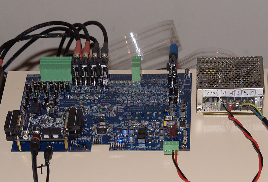
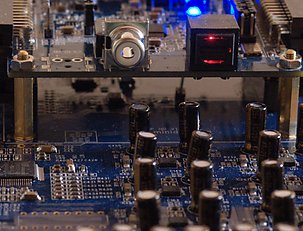
miniDSP 2x8 with miniDIGI
With that all done, I was able to sit back and play some music!
Going digital
With the analog inputs set up already, I decided to press on and get the digital input going. My 2×8 board came with the (optional) miniDIGI daughter board already mounted, as shown at lower left in the photograph above. Checking the jumpers on the miniDIGI board against the miniDIGI User Manual showed that the miniDIGI came configured to accept input on TOSLINK input #1. So I moved the jumper to select S/PDIF input #1, connected the output of a USB to S/PDIF converter to that input on the miniDIGI, and slowly ramped up the volume in iTunes. Et voila!
For USB playback (via an S/PDIF converter), volume can be controlled in the player on the computer. If connecting a CD player, though, a caution is warranted: simply plugging a CD player into the S/PDIF input will result in playback at FULL VOLUME! Not good. The levels can be adjusted using the input channel sliders on the Input screen. A more convenient solution would be to use the “Master Volume” digital volume control function, which requires connecting an external 10k potentiometer to three pins on the board. (I’ll report on this in a later issue.)
Note: Make sure all power is off when changing jumpers and making connections. The USB cable can be connected and disconnected while power is on, but I strongly recommend turning off all the power for any other connections.
Note also: I recommend turning your power amps off before turning off the miniDSP, as the DSP generates a transient noise when it loses power. (A solution to this may be available using the REM IN muting input connector on the board. For now, though, I prefer to play it safe.)
Closing remarks
Well, that was fun! Although it’s early days with the new board, it has definitely found a home in my main system. In the next article in this series, I’ll get back to the dipole system in earnest and get the promised dipole subs running. In the meantime, if you have specific questions about the 2×8 board or the 4×10 plug-in, please feel free to ask below and I’ll try to answer them. And you can, of course, also ask questions on the miniDSP user forum.
Acknowledgements
I’d like to thank the following people who helped improve this article: Rod Mell, Paul Chapkin, Norman Tracy of Audio Crafter’s Guild, and Tony Rouget of miniDSP.


Nice write up, board looks good but any noticible difference in audio quality compared to the 2×4?
Hi Ken, thanks for the comment! I don’t think I can offer a meaningful “apples to apples” comparison, as I was not using the digital card with the 2x4s, and there were some small changes in the EQ in the transfer. And swapping back and forth between boards to compare just isn’t feasible. Once the system is “dialled in” though I plan to try and set up some sort of “listening panel” to offer an unbiased opinion on the overall result. Hopefully that will prove interesting for everybody! Thanks again 🙂
Fantastic write up!
I have just received my own 2×8 and mounted it into a simple aluminium chassis. So far I am only using it as a DAC, taking the optical toslink from my laptop into the minidig, and ouputting this to my integrated amp. This provides me a direct comparison to the analogue out from my soundcard. I am surprised by the quality considering it isn’t a standalone DAC! There is tremendous clarity in the mid and high end and the bass is full and punchy – especially when playing my 24/96 vinyll recordings.
I intend to run the minidigi as a ‘digital preamp and crossover’ so will be adding input selection and volume control, as well as a digital/analogue selector switch to take the outputs of my turntable pre-amp. This will feed class D/T power amps to run a fully active 2 way plus stereo sub system, perhaps even a four way in the future.
One thing I am interested in, considering I have no external soundcard for my laptop, is the possibility of using the analogue in and digital out to perform room EQ’ing. I would like to route the output of the computer through the digital in via usb, playing through the speakers. This would be recorded by the microphone/pre-amp into the analogue in, which would be routed to the digital out and to the usb of the computer. I have the ministreamer mounted into the same case, I just need to find out if it can perform full duplex – IE record and playback at the same time. Can you see this working?
Many thanks for the articles. I hope to write my experiences as you have as I go along!
Regards,
Jai
Thanks Jai for the comment. That’s a very interesting idea with the measurement setup! In thinking it through, I am not sure if it will work, because a) the SPDIF output from the miniDIGI will be running at 96 kHz, and b) the miniStreamer will not run full-duplex at 96 kHz, as I understand it. It “might” be possible to run the miniStreamer at 96 kHz in and 44.1 kHz out… I think it might just have to be tried to see if it works. I do have a miniStreamer here but it’s not connected into the system yet.
I’ve recently read that too.. Thinking about it, I might be able to send the signal to the minidsp via the toslink out from my laptop, and use the ministreamer in single duplex 24/96. That would depend on either windows or REW being able to use two devices at the same time. IE the internal soundcard to output the sweeps and the ministreamer as a recording device. I will have to look into it. I’d like to save the expense of an external soundcard if I can help it.
On another note: Do you have any advice on what type of power supply I should look for? I have gutted a wall-wart 12v PSU and fitted it into my case as a temporary measure, but it isn’t able to deliver the full 1.5A as per the specification sheet. At the moment I’m only running one set of S/E outputs so I’m sure it’s fine; but later if I decide to run the full compliment of balanced 8channel outputs I’m sure I would run into problems. I’d like to have two clean power supplies: One 12V for the minidsp and one 5V for the ministreamer.
Hi Jai, the only PSU I’ve used with the 2×8 so far is a small SMPS, I think it’s a Meanwell. I don’t think the number of outputs being used will make very much of a difference to the current draw. If you’d like to build a linear PSU a 9V transformer with a fullwave bridge and reasonable capacitance should work well, as regulation is on the 2×8 board. Add a 5V regulator for the miniStreamer. That would be what I would prototype anyway.
Sweeet, i’ve been looking for an all digital method to bypass my crossovers for some time and here it is.
2 q’s. 1- do i still need my pre-amp?
2- As it has been a few months since this article, have you found any suitable Chassis yet (prefab) or do i need to make one?
Thank you so much for this write up, I love the site.
Hi George, if it’s all-digital e.g. a computer source with volume control, then you wouldn’t use a preamp. No chassis yet, the miniDSP folks said they would make one a long time ago but none has been sighted yet.
Just a reminder that for those who weren’t aware of it, there is a case for the MiniDSP 2×8 available now. It is basically the same case as the 4×10 case. It lists for $99.00 on the company’s website.
Thanks for the note Brad. It’s a bit buried on the site, here’s a direct link: http://www.minidsp.com/products/accessories/misc-accessories/minidsp-2×8-8×8-box-detail
Just want to add a source for inexpensive power supply. I’m using the Welland PA-215 that came with my external hard drive enclosure. It works quite nicely. These are available for about $US 12.00 to $15.00 if you search the Web. You might convince a local computer store, but make sure it’s the right model.
It’s a switching adapter. It comes with a 4-pin Mini-DIN connector and outputs 12V @ 1.8A and 5V @ 1.5A, so it’ll supply all the basics for the MiniDSP 2×8. I measured 12.3V and 5.01V with a DMM with no load. A few others reported using these and said they heard no noise. YMMV.
Brad
Oops! Want to clarify something from my above post: If I remember correctly when the MiniDIGI is mounted as a stack on top of the MiniDSP 2×8 board (and with the ribbon cables), it does not require a separate 5V feed. I believe it only requires that when it is not connected to the main MiniDSP board.
Also, sorry if for the typos in my above post. John, please feel free to correct them. (IF only this software allowed you to edit posts).
Thanks for the note Brad! I’m afraid that the commenting system is not very sophisticated…
I can confirm that the miniDIGI when piggybacked on the main board doesn’t require a separate supply.